Tensor-sparse-representation-based MIMO radar's imaging method

A radar imaging and sparse representation technology, which is applied in the field of radar technology and signal processing, can solve the problems of unable to remove the base signal, reduce the performance of the method, and destroy the multi-dimensional structure of the signal, so as to overcome low resolution and high sidelobe, avoid signal The effect of loss of intrinsic structural information

Active Publication Date: 2017-05-17
HARBIN ENG UNIV
View PDF5 Cites 20 Cited by
  • Summary
  • Abstract
  • Description
  • Claims
  • Application Information

AI Technical Summary

Problems solved by technology

This method has a lower computational load and higher imaging resolution, but since the OMP method can only expand the strategy of not removing the bad base signal when selecting the base signal, the OMP recovery method will have artifacts in radar imaging applications point, which is not conducive to the identification of the target
The literature (Subspace pursuit for compressive sensing signal recomstruction.IEEE Transaction on Information Theory,2009,55(5):2230-2249) proposes a compressed sensing greedy method called subspace pursuit (subspace pursuit, SP), which corrects the OMP The method has the problem of artifact points, but its resolution is lower than the OMP method in MIMO radar imaging applications
[0005] In addition, the sparse imaging method mentioned above usually processes the received signal as a stack, which will undoubtedly destroy the multi-dimensional structure of the signal, so that the multi-dimensional structure information of the signal cannot be used, resulting in a decrease in the performance of the method
Especially in the case of low signal-to-noise ratio and small samples, the performance is even worse

Method used


Image

  • Tensor-sparse-representation-based MIMO radar's imaging method
  • Tensor-sparse-representation-based MIMO radar's imaging method
  • Tensor-sparse-representation-based MIMO radar's imaging method

Examples


Embodiment Construction

[0068] The present invention will be further described below in conjunction with the accompanying drawings.

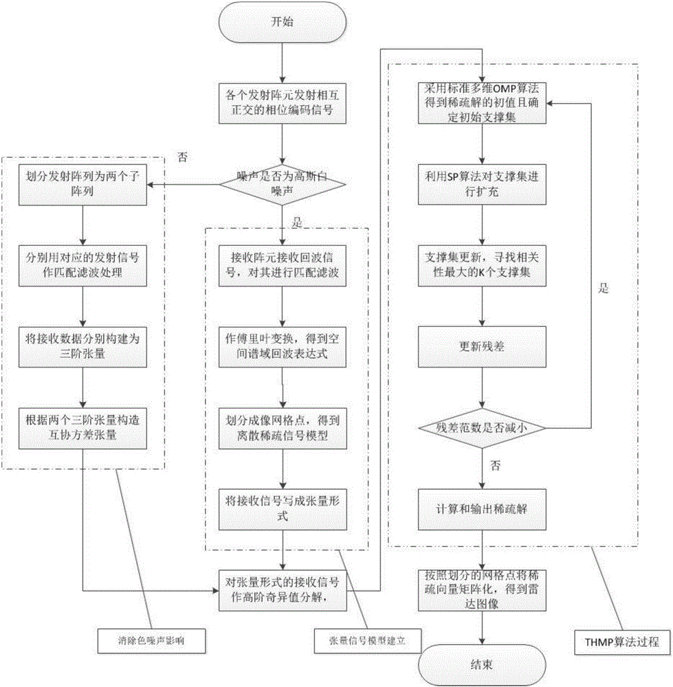
[0069] The purpose of the present invention is to overcome the defects of the above-mentioned technologies, and propose a MIMO radar sparse imaging method based on tensor mix-and-match tracking. This method utilizes the multi-dimensional structure of MIMO radar received signals, and performs high-order singular value decomposition to obtain multi-dimensional linear measurement results. Then under the framework of sparse signal recovery, the advantages of OMP method and SP method are combined, so that it guarantees the orthogonality when selecting the base signal, and adopts the backtracking strategy when updating the support set. Through this operation, the proposed method can guarantee a high resolution of radar image reconstruction without artifacts at the cost of a certain amount of computation.

[0070] The imaging method of the present invention mainly comprises ...


PUM


Abstract

The invention belongs to the radar technology field and signal processing field and more particularly, to a tensor-sparse-representation-based MIMO radar's imaging method for a multi-input and multi-output type system. The method comprises: transmitting by M emission array elements mutually orthogonal phase coded signals; receiving by N receiving array elements the phase coded signals; using a matched filter to perform matched filtering to the received radar signals; conducting the Fourier transform to the signals after matched filtering to obtain the spatial spectral echo expression; performing mesh generation to the scene; and discretizing the radar echoes to obtain the mathematical expression for radar imaging and focusing under the compression sensing framework. The method of the invention overcomes the shortcoming of a DAS method which has intrinsically low resolutions and high side lobes. Compared with other classic imaging method featuring compression sensing, the THMP method of the invention fully utilizes the tensor characteristics of received signals to conduct sparse signal recovery, which avoids the information loss of the internal structure of the signals brought about by the vectorized operations.

Description

technical field [0001] The invention belongs to the technical field of radar and the field of signal processing, in particular to a MIMO radar imaging method based on tensor sparse representation for a multi-input multi-output type system. Background technique [0002] Multiple-input multiple-output (MIMO) radar is a new radar system emerging in the 21st century, which uses multiple transmitting and receiving antennas to observe targets simultaneously. Good array configuration design and waveform diversity technology enable MIMO radar to obtain observation channels and spatial degrees of freedom far more than the actual number of physical array elements, which can significantly improve the identifiability of parameters and achieve a more flexible emission pattern designed to improve object detection and parameter estimation performance. Compared with traditional imaging radar, MIMO radar has obvious performance advantages in imaging azimuth resolution, real-time and motion ...

Claims


Application Information

Patent Timeline
Patent Type & Authority Applications(China)
IPC IPC(8): G01S13/89
CPCG01S13/89
Inventor 王伟张斌李欣魏振宇
Owner HARBIN ENG UNIV
Why Eureka
Try Eureka