
Unmanned aerial vehicle (UAV) obstacle avoidance method and system based on binocular vision and optical flow fusion

A binocular vision, unmanned aerial vehicle technology, applied in image data processing, instruments, 3D position/channel control and other directions, can solve the problems of difficult obstacle avoidance, expensive FPGA, difficult to apply, etc., to simplify the obstacle avoidance process, The effect of improving operation speed and improving real-time performance

Inactive Publication Date: 2017-05-17
NANJING UNIV OF AERONAUTICS & ASTRONAUTICS
View PDF9 Cites 56 Cited by
  • Summary
  • Abstract
  • Description
  • Claims
  • Application Information

AI Technical Summary

Problems solved by technology

Although FPGA has the characteristics of small size and fast operation speed, FPGA is expensive and requires a special development language for programming, which is not conducive to docking with other modules
Moreover, the patent only describes the hardware architecture of UAVs using binocular vision for obstacle detection, and does not explain the specific algorithm of how to detect obstacles.
[0010] Therefore, although there are many researches in the field of obstacle avoidance using binocular vision at home and abroad, most methods cannot quickly obtain the position and speed of obstacles relative to the UAV, and it is difficult to quickly and accurately avoid obstacles. Most of them are difficult to apply to the field of UAV real-time obstacle avoidance

Method used


Image

  • Unmanned aerial vehicle (UAV) obstacle avoidance method and system based on binocular vision and optical flow fusion
  • Unmanned aerial vehicle (UAV) obstacle avoidance method and system based on binocular vision and optical flow fusion
  • Unmanned aerial vehicle (UAV) obstacle avoidance method and system based on binocular vision and optical flow fusion

Examples


Embodiment Construction

[0043] Embodiments of the invention are described in detail below, examples of which are illustrated in the accompanying drawings. The embodiments described below by referring to the figures are exemplary only for explaining the present invention and should not be construed as limiting the present invention.

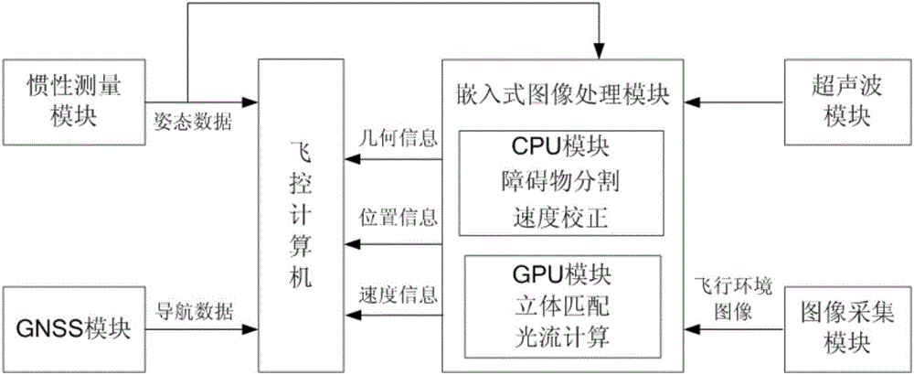
[0044] Such as figure 2 As shown, it is a hardware structural diagram of the UAV obstacle avoidance system based on binocular vision and optical flow fusion of the present invention. The system includes an image acquisition module, an embedded image processing module, a flight control computer, an ultrasonic module, and a GNSS (Global Navigation Satellite System global satellite navigation system) module and inertial measurement module, wherein the embedded image processing module includes a CPU module and a GPU module, and the ultrasonic module includes four ultrasonic sensors, which are installed in the front, rear, left and right directions of the drone The ultrason...


PUM


Abstract

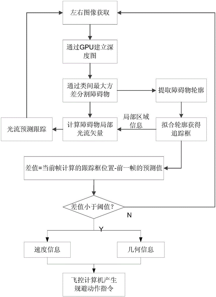
The invention discloses an unmanned aerial vehicle (UAV) obstacle avoidance method and system based on binocular vision and optical flow fusion. The method includes the steps of obtaining image information through an airborne binocular camera in real time; obtaining image depth information by using the graphics processing unit (GPU); extracting geometric contour information of the most threatening obstacle by using the obtained depth information and calculating the threat distance by a threat depth model; obtaining an obstacle tracking window by the rectangular fitting of the geometric contour information of the obstacle and calculating the optical flow field of the area to which the obstacle belongs to obtain the velocity of the obstacle relative to the UAV; and sending out an avoidance flight action instruction by a flight control computer to avoid the obstacle according to the calculated obstacle distance information, the geometric contour information and the relative velocity information. The invention realizes effective fusion of the depth information of the obstacle and the optical flow vector, obtains the movement information of the obstacle relative to the UAV in real time, improves the ability of the UAV to realize the visual obstacle avoidance, and enables a greater increase in the real-time performance and accuracy as compared with traditional algorithms.

Description

technical field [0001] The invention relates to an obstacle avoidance method for an unmanned aerial vehicle, in particular to an obstacle avoidance method and system for an unmanned aerial vehicle based on fusion of binocular vision and optical flow, and belongs to the technical field of obstacle avoidance for an unmanned aerial vehicle. Background technique [0002] With the development of UAV technology and its application market, UAVs are often faced with special tasks that are different from the past, and these tasks put forward higher requirements for their ability to quickly identify and avoid obstacles on the way. Because the vision-based obstacle avoidance system usually adopts a passive working mode, it has the characteristics of simple equipment, low cost, good economy, and wide application range. [0003] Compared with the obstacle avoidance system based on active sensors such as ultrasonic waves and lidar, the visual obstacle avoidance system has faster response ...

Claims


Application Information

Patent Timeline
IPC IPC(8): G05D1/10G06T7/70G06T7/564
Inventor 张天翼杨忠胡国雄韩家明张翔沈杨杨
Owner NANJING UNIV OF AERONAUTICS & ASTRONAUTICS
Learn More