
System and method for controlling and optimizing hydrogen utilization factor of alloy hydrogen-storage fuel cell

A technology of fuel cells and fuel cell units, which is applied in the direction of fuel cells, circuits, electrical components, etc., can solve the problems of reduced hydrogen discharge capacity of hydrogen storage tanks, unusable hydrogen storage capacity, and reduced fuel cell power, achieving simple system, The effect of optimizing the effective hydrogen release amount and improving the utilization efficiency

Active Publication Date: 2017-05-17
GRIMAT ENG INST CO LTD
View PDF5 Cites 11 Cited by
  • Summary
  • Abstract
  • Description
  • Claims
  • Application Information

AI Technical Summary

Problems solved by technology

At present, alloy hydrogen storage tanks suitable for base station backup power supply mainly use AB (such as TiFe) and AB2 (such as TiMn2) hydrogen storage alloys. These alloys have a hydrogen depletion platform that can deplete a large amount of hydrogen in a specific small pressure range. The platform pressure As the temperature of the alloy rises and falls, when the temperature is lower than a certain point, the platform pressure will be lower than the atmospheric pressure and a large amount of hydrogen storage capacity cannot be used
Although there have been studies on the design of using the waste heat of the fuel cell to heat the hydrogen storage tank, there is no monitoring of the specific temperature of the hydrogen storage alloy and the adjustment of the cooling system of the fuel cell. The amount of hydrogen decreases, and the insufficient hydrogen supply will lead to a reduction in the power of the fuel cell, which will further reduce the heat supply. In the end, there will be a large amount of hydrogen left in the hydrogen storage tank, but the temperature is too low to release it, resulting in the premature shutdown of the fuel cell.

Method used


Image

  • System and method for controlling and optimizing hydrogen utilization factor of alloy hydrogen-storage fuel cell

Examples


Embodiment Construction

[0018] A detailed description will be given below in conjunction with the accompanying drawings.

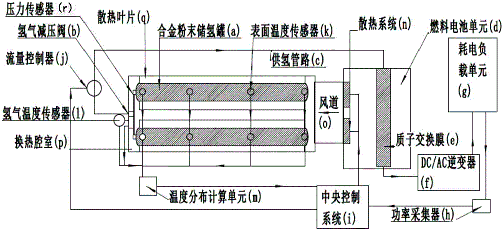
[0019] attached figure 1 Design structure diagram for alloy hydrogen storage-fuel cell power generation backup power system, such as figure 1 As shown, the system includes alloy hydrogen storage unit, fuel cell unit d, temperature distribution calculation unit m, central control system i, power collector h, power consumption load unit g, DC / AC inverter f; alloy hydrogen storage unit Including alloy powder hydrogen storage tank a, heat exchange chamber p, surface temperature sensor k, air duct o, heat dissipation blade q, hydrogen temperature sensor l, flow controller j, hydrogen pressure reducing valve b, pressure sensor r, hydrogen supply pipe Road c; fuel cell unit d including proton exchange membrane e, cooling system n; alloy powder hydrogen storage tank a, hydrogen pressure reducing valve b, hydrogen pipeline c fuel cell unit d, DC / AC inverter f, power consumption load Uni...


PUM


Abstract

The invention belongs to the technical and control field of fuel cells, and in particular relates to a system and method for controlling and optimizing hydrogen utilization factor of an alloy hydrogen-storage fuel cell. The problem that a large amount of hydrogen reserves are wasted since the effective hydrogen utilization efficiency of an alloy hydrogen-storage tank cannot achieve the optimal is solved. The invention provides a system and method for controlling and optimizing hydrogen utilization factor of an alloy hydrogen-storage fuel cell. The system comprises an alloy hydrogen-storage unit, a fuel cell unit d, a temperature distribution computing unit m, a central control system I, a power acquirer h, a power consumption loading unit g and a DC / AC inverter f. The optimal hydrogen desorption temperature and the heat required for maintaining the temperature are computed through a hydrogen desorption PCT curve of the hydrogen-storage alloy and the heat conductivity of a hydrogen-storage alloy powder block body, and then the heat supply of a fuel cell radiation system is adjusted to warm the hydrogen-storage alloy tank, the effective hydrogen desorption amount of the alloy hydrogen-storage tank is maximally optimized, and the hydrogen utilization efficiency is greatly improved.

Description

technical field [0001] The invention belongs to the field of fuel cell technology and control, in particular to a system and method for controlling and optimizing the hydrogen utilization rate of an alloy hydrogen storage fuel cell. Background technique [0002] Fuel cell power supply is widely used in emergency backup power supply in the field of communication, and can also be used as an independent power supply in areas where the power grid is not convenient. Fuel cells convert the electrochemical energy of fuel into electricity with a much higher efficiency than internal combustion engines. It is the best choice to use hydrogen energy as fuel for fuel cells. Hydrogen energy is regarded as the clean energy with the most development potential in the 21st century. Its main advantages lie in cleanliness and high efficiency. Hydrogen has a high combustion calorific value, and the product of combustion is water. It is the cleanest energy in the world. Hydrogen can also be pro...

Claims


Application Information

Patent Timeline
IPC IPC(8): H01M8/04089H01M8/0432H01M8/04313H01M8/0606
CPCH01M8/04089H01M8/04313H01M8/0432H01M8/0606Y02E60/50
Inventor 卢淼
Owner GRIMAT ENG INST CO LTD
Learn More