A crystal oscillator frequency debugging system

A technology of crystal oscillators and debugging systems, applied in automatic control of power, electrical components, etc., can solve problems such as relatively high welding technology requirements, hidden dangers left by products, and low production efficiency, so as to reduce reliability risks, fast and accurate Frequency accuracy debugging and the effect of improving production efficiency

Active Publication Date: 2020-03-31
GUANGDONG DAPU TELECOM TECH CO LTD
View PDF5 Cites 0 Cited by
  • Summary
  • Abstract
  • Description
  • Claims
  • Application Information

AI Technical Summary

Problems solved by technology

[0004] This method realizes the frequency accuracy debugging of the crystal oscillator through multiple debugging, but it has relatively high requirements on the welding technology of the operator, and the repeated welding is easy to leave hidden dangers to the product, and there are also disadvantages such as long debugging time and low production efficiency. place

Method used


Image

  • A crystal oscillator frequency debugging system
  • A crystal oscillator frequency debugging system
  • A crystal oscillator frequency debugging system

Examples


Embodiment 1

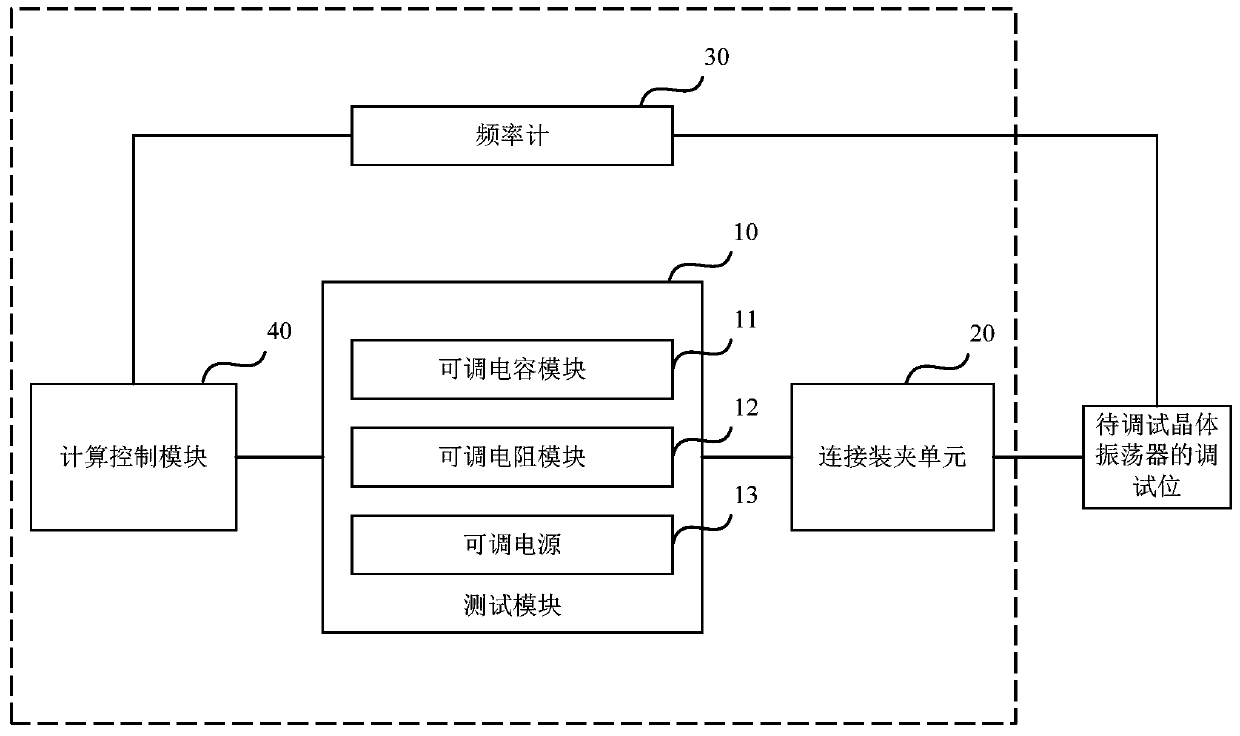
[0032] figure 1 It is a schematic diagram of a crystal oscillator frequency debugging system provided by Embodiment 1 of the present invention. Such as figure 1 As shown, the embodiment of the present invention provides a crystal oscillator frequency debugging system. By simulating and changing the resistance and capacitance parameters of the debugging bit of the crystal oscillator to be debugged, fast and accurate frequency accuracy debugging is realized, which solves the problem of the operator in the debugging process. The potential safety hazards and low production efficiency caused by repeated welding to the product.

[0033] The crystal oscillator frequency debugging system includes a test module 10, including an adjustable capacitor module 11, an adjustable resistance module 12 and an adjustable power supply 13;

[0034] Connect the clamping unit 20, the input end of the connecting clamping unit 20 is respectively connected to the output end of the adjustable capacita...

Embodiment 2

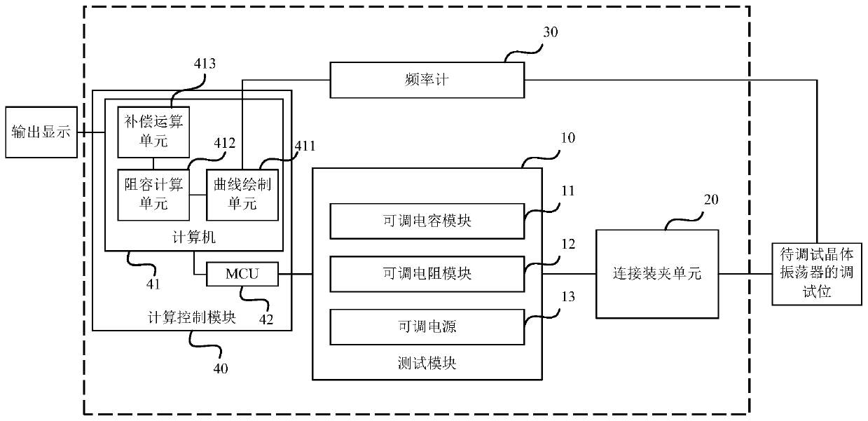
[0053] figure 2 It is a schematic diagram of a crystal oscillator frequency debugging system provided by Embodiment 2 of the present invention. The system is based on the first embodiment, the calculation control module 40 includes a computer 41, MCU42; the computer 41 can realize the following functional units through software and / or, the functional units include a curve drawing unit 411, a resistance-capacitance calculation The unit 412 preferably also includes a compensation calculation unit 413 .

[0054] The compensation calculation unit 413 is connected to the resistance-capacity calculation unit 412, and is used to retrieve the compensation value entered in the index library according to the information of the crystal oscillator to be debugged, and use the compensation value to calculate the target resistance and the target resistance. The capacitance is compensated.

[0055] It should be noted that since the actual resistance-capacitance effect of the product is sli...


PUM


Abstract

The invention discloses a crystal oscillator frequency debugging system. The system includes: a test module which includes an adjustable capacitance module, an adjustable resistance module and an adjustable power supply; a connection clamping unit which has an input end and an output end, wherein the input end is in separate connection to the output ends of the adjustable capacitance module, the adjustable resistance module and the adjustable power supply, and the output end is intended for connecting a debugging bit of a to-be-debugged crystal oscillator; a frequency meter which is intended for connecting the to-be-debugged crystal oscillator and reading frequencies; a computing control module which is connected to a control end of the test module and the frequency meter and is intended for separately outputting capacitance control parameters, resistance control parameters and power control parameters to the adjustable capacitance module, the adjustable resistance module and the adjustable power supply so as to form required capacitance, resistance and power value which are to be loaded to the debugging bit of the to-be-debugged crystal oscillator, reading the frequency of the to-be-debugged crystal oscillator and adjusting the capacitance control parameters. According to the invention, the crystal oscillator frequency debugging system optimizes production procedures and increases production efficiency.

Description

technical field [0001] Embodiments of the present invention relate to the technical field of crystal oscillators, in particular to a frequency debugging system for crystal oscillators. Background technique [0002] Crystal oscillator is a high-precision and high-stability oscillator, which is widely used in various oscillating circuits such as color TVs, computers, remote controls, and as a frequency generator in communication systems to generate clock signals and Provides a reference signal for a specific system. [0003] At present, the general method for debugging the frequency accuracy of crystal oscillators in the industry is: reserve a debugging bit on the crystal oscillator to be debugged, and use it for subsequent debugging stations to weld frequency accuracy debugging capacitors and voltage-controlled debugging resistors; At the same time, by manually reading the frequency of the frequency meter and comparing the frequency value required by the specification, the o...

Claims


Application Information

Patent Timeline
Patent Type & Authority Patents(China)
IPC IPC(8): H03L7/00H03L5/00
CPCH03L5/00H03L7/00
Inventor 王伟刘朝胜周柏雄
Owner GUANGDONG DAPU TELECOM TECH CO LTD
Why Eureka
Try Eureka