Piezoelectric dispenser with a longitudinal transducer and replaceable capillary tube

A capillary and distributor technology, applied in chemical instruments and methods, injection devices, fluid controllers, etc., to achieve large distribution flexibility, eliminate the need for cleaning, and avoid degradation

Active Publication Date: 2017-05-17
BIODOT
View PDF9 Cites 6 Cited by
  • Summary
  • Abstract
  • Description
  • Claims
  • Application Information

AI Technical Summary

Problems solved by technology

This allows the tube to be remove

Method used


Image

  • Piezoelectric dispenser with a longitudinal transducer and replaceable capillary tube
  • Piezoelectric dispenser with a longitudinal transducer and replaceable capillary tube
  • Piezoelectric dispenser with a longitudinal transducer and replaceable capillary tube

Examples


Embodiment Construction

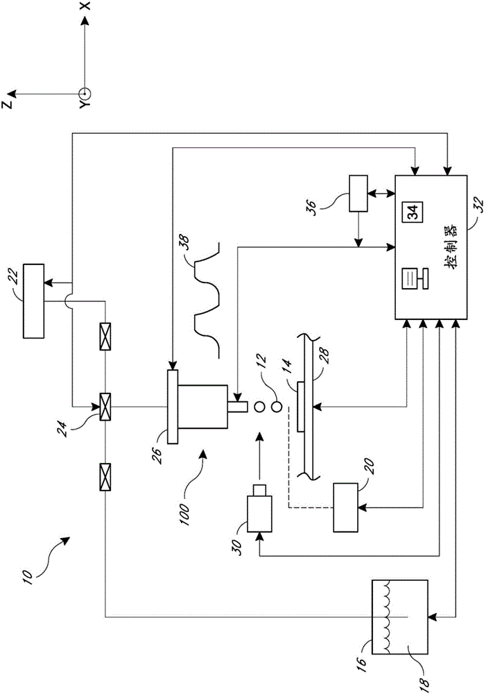
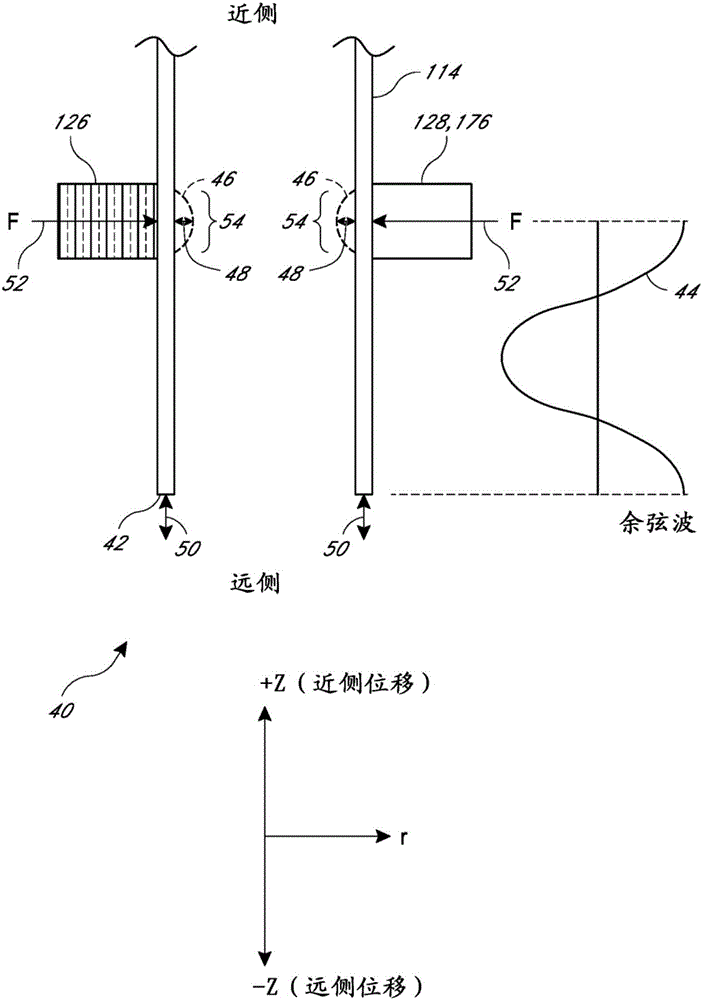
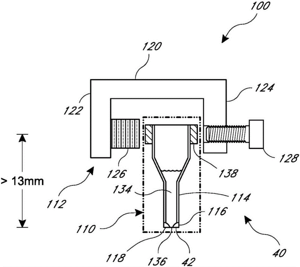
[0119] Embodiments described herein relate generally to systems and methods for acquiring and non-contactingly dispensing predetermined volumes of liquid, and in particular to acquiring and dispensing volumes of liquid—particularly but not exclusively for use in Dispensing and delivering small volumes of fluids such as for the automated production of DNA arrays or multiplexing assays—unique piezoelectric dispensing devices in which the liquid is dispensed in the form of individual droplets having volumes of, for example, on the order of picoliters to nanoliters drop. Embodiments of the dispensing device advantageously utilize disposable, detachable or detachable capillary assemblies while desirably maintaining the piezoelectric actuator or transducer further for subsequent use, thereby reducing the potential for cross-contamination of fluids and provide an economical and cost-effective method of reusing piezoelectric actuators or transducers for further manipulations such as d...


PUM


Abstract

A dispenser and methods for transferring liquids are disclosed. The dispenser may include a capillary tube with tip having an aperture, a piezoelectric actuator coupled to the capillary tube at a location. Actuation of the piezoelectric actuator causes a pressure wave to propagate along the capillary tube toward the tip such that radial motion at the location is transmitted as distally extending axial motion of the tip, thereby causing a droplet of a predetermined volume to be ejected from the aperture. In some embodiments, the capillary tube has a modulus of elasticity in a range which dampens acoustical noise from the actuation and provides single drop stability over a range of drop sizes.

Description

Background technique [0001] The disclosed embodiments generally relate to systems and methods for acquiring and dispensing predetermined volumes of liquid, and more particularly, but not exclusively, to systems and methods for dispensing and delivering small volumes, typically volumes in the form of individual droplets or droplets. Piezoelectric devices and methods for fluids in the picoliter to nanoliter range. [0002] Conventional piezo dispensing devices have a tube that is usually completely surrounded by and coupled to a piezo actuator to produce droplets. Activation of the piezoelectric actuator transmits sound pressure into and through the liquid in the tube. The sound pressure propagates through the liquid and reaches the dispensing opening of the tube. This causes droplets to be ejected from the device. [0003] Such conventional devices have several disadvantages. One disadvantage is that the operation of such conventional devices is highly dependent on the char...

Claims


Application Information

Patent Timeline
IPC IPC(8): B05B17/06
CPCB01J2219/00367B01J2219/00378B01L3/0268B01L2300/0838B01L2300/123B01L2300/165B01L2400/0481B05B17/0684B05B17/0669B01J2219/00722B01J19/0046
Inventor 耶胡达·伊夫里托马斯·C·蒂索内埃里克·P·国沙恩·贡萨卢斯
Owner BIODOT
Why Eureka
Try Eureka