Welding gun device of soldering equipment

A welding equipment and welding torch technology, applied in the field of welding equipment, can solve problems such as insufficient bonding between the soldering iron tip and the welding product, defective products exceeding the standard, and scratches on the soldering iron tip, so as to improve product quality and yield rate, and reduce the risk of damage cost, the effect of ensuring quality requirements

Pending Publication Date: 2017-05-24
江苏洛柳精密科技有限公司
View PDF4 Cites 11 Cited by
  • Summary
  • Abstract
  • Description
  • Claims
  • Application Information

AI Technical Summary

Problems solved by technology

[0002] The existing welding torch welding device moves up and down perpendicular to the welding product pins for welding action, which cannot effectively contact the product pins for heat transfer; on the other hand, the previous welding torch devices cannot achieve accurate real-time temperature control, so that high-quality The welding effect and precise welding requirements, resulting in defective products exceeding the standard; and the ordinary welding torch device does not take any buffer measures during the lifting process, and completely depends on the Z-axis lifting of the welding platform to realize the contact between the soldering iron tip and the welding product. If the Z-axis drop does not reach a certain height, it is very easy to cause the soldering iron tip and the welding product to not fit tightly enough, and effective welding cannot be completed; in addition, if the Z-axis drop height of the platform is too high, and there is no effective buffer method, it will cause Scratching of the soldering iron tip to the soldering product and impact damage to the soldering iron tip itself

Method used


Image

  • Welding gun device of soldering equipment
  • Welding gun device of soldering equipment
  • Welding gun device of soldering equipment

Examples


Embodiment Construction

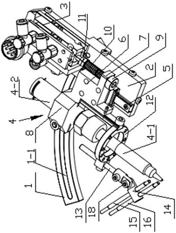
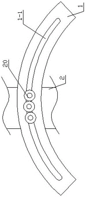
[0019] Such as figure 1 , 2 , 3, and 4, the present invention includes an arc-shaped fixing bracket 1, a welding torch base 2, a lifting cylinder 3 and a welding torch assembly 4, the arc-shaped fixing bracket 1 is fixed on the welding platform, and the arc-shaped fixing bracket 1 is provided with an arc-shaped groove 1-1, the position of the center of the arc-shaped groove 1-1 is the position of the welding point of the product, the first bolt 20 is arranged in the arc-shaped groove 1-1, the back of the welding torch base 2 and the first bolt 20 in the arc-shaped groove 1-1 A bolt 20 is threaded so that the welding torch base 2 can slide relative to the arc-shaped groove 1-1, and the first bolt 20 can also be tightened to fix the welding torch base 2 and the arc-shaped fixing bracket 1 as one.

[0020] A vertical slide rail 5 is installed on the welding torch base 2, and a sliding seat 6 is slidably installed on the sliding rail 5. One side of the sliding seat 6 is integrall...


PUM


Abstract

The invention provides a welding gun device of soldering equipment, and relates to the field of welding equipment. The welding gun device comprises an arc-shaped fixed support, a welding gun base, a lifting cylinder and a welding gun assembly. An arc-shaped groove is formed in the arc-shaped fixed support. A bolt is arranged in the arc-shaped groove. The back side of the welding gun base is connected with the bolt in the arc-shaped groove in a threaded mode so that the welding gun base can slide relative to the arc-shaped groove, and the welding gun base and the arc-shaped fixed support can be fixed into a whole by screwing the bolt. The welding gun assembly is mounted on the welding gun base in a vertical sliding mode. The lifting cylinder is mounted on the welding gun base and used for driving the welding gun assembly to slide along the welding gun base. According to the welding gun device of the soldering equipment, the welding gun base can slide relative to the arc-shaped sliding groove in the arc-shaped fixed support, and a welding gun is made to incline relative to a welded product so that tin can be fed conveniently, a welding head can be closely attached to the welded product effectively, a sufficient heat transmission is achieved, the quality and qualification rate of products are greatly increased accordingly, and pseudo soldering and soldering omission are completely eradicated.

Description

technical field [0001] The invention relates to the field of welding equipment, in particular to a welding torch device of soldering equipment. Background technique [0002] The existing welding torch welding device moves up and down perpendicular to the welding product pins for welding action, which cannot effectively contact the product pins for heat transfer; The welding effect and precise welding requirements, resulting in defective products exceeding the standard; and the ordinary welding torch device does not take any buffer measures during the lifting process, and completely relies on the Z-axis lifting of the welding platform to realize the contact between the soldering iron tip and the welding product. If the Z-axis drop does not reach a certain height, it is very easy to cause the soldering iron tip and the welding product to not fit tightly enough, and effective welding cannot be completed; in addition, if the Z-axis drop height of the platform is too high, and th...

Claims


Application Information

Patent Timeline
Patent Type & Authority Applications(China)
IPC IPC(8): B23K3/00B23K3/06B23K3/08B23K37/02
CPCB23K3/00B23K3/063B23K3/08B23K37/0252
Inventor 黄稳岩黄志军
Owner 江苏洛柳精密科技有限公司
Why Eureka
Try Eureka