Eureka AIR delivers breakthrough ideas for toughest innovation challenges, trusted by R&D personnel around the world.

Method for cooling air leaking flange of supporting plate of hot blast valve

A technology of hot blast valve and flange, which is applied in the direction of furnace, furnace type, blast furnace parts, etc., can solve the problems of increasing spare parts cost and maintenance cost, affecting blast furnace output, blast furnace long shutdown, etc., so as to reduce spare parts consumption and avoid Stop the wind accident and ensure the effect of smooth progress

Inactive Publication Date: 2017-05-24
ANGANG STEEL CO LTD
View PDF2 Cites 2 Cited by
  • Summary
  • Abstract
  • Description
  • Claims
  • Application Information

AI Technical Summary

Problems solved by technology

At the beginning of 2015, there was an air leakage phenomenon in the flange of the lower support plate of the hot air valve of the blast furnace hot blast stove. The length of the air leakage was 400mm. There was an empty flange seal that had been blown out. The temperature of the air leakage reached 450°C, and there was a danger of burning through at any time
The working environment of the hot air valve operates under high temperature, high pressure, and high oxygen-enriched conditions, and the structure of the hot air valve itself is very complicated, and there are many flanges with a water-cooled structure, so the probability of air leakage is extremely high. Once an air leak occurs somewhere, it cannot be handled properly. It will lead to the blast furnace long shutdown accident, seriously affect the blast furnace output, and increase the cost of spare parts and maintenance costs

Method used


Image

  • Method for cooling air leaking flange of supporting plate of hot blast valve

Examples


Embodiment Construction

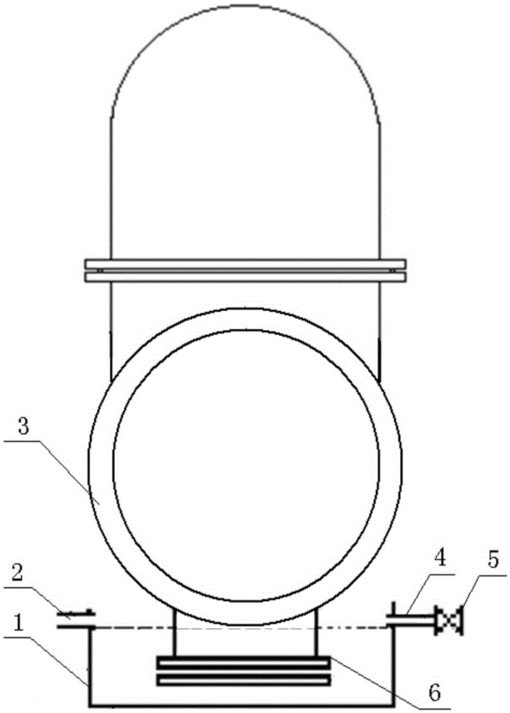
[0018] The cooling method of the air leakage of the flange of the hot air valve supporting plate of the present invention is as follows:

[0019] 1. Wrap the thin copper strands around the air leakage of the flange 6 of the supporting plate first, and apply force by fastening the bolts of the flange 6 to reduce the air leakage.

[0020] 2. Weld an open cooling water tank 1 with a 5 mm thick steel plate on the lower bracket of the hot air valve 3, and the upper edge of the cooling water tank 1 is 100 mm higher than the upper surface of the flange 6 that leaks air, so that the flange 6 can be fully immersed in the cooling water in the water.

[0021] 3. Weld a replenishing water pipe 4 with an outer diameter of 15mm on the upper right side of the cooling water tank 1, and install a ball valve 5 on the replenishing pipe 4 to control the replenishing water flow. The rear end of the ball valve 5 is connected with a cloth rubber hose with an inner diameter of 15mm, and the other en...


PUM

PropertyMeasurementUnit
diameteraaaaaaaaaa

Abstract

The invention provides a method for cooling an air leaking flange of a supporting plate of a hot blast valve. The method comprises the following steps: winding an air leaking position by using a thin copper wire strand at first, and fastening and stressing through bolts of the flange; welding a cooling water tank to the lower part of the hot blast valve, and enabling the upper edge of the cooling water tank to be higher than the air leaking flange; respectively welding a water replenishing tube and a water draining tube to the upper part of the cooling water tank; connecting the water replenishing tube to a water tube through a ball valve and a cloth inserted hose, and meanwhile welding an overflow tube to the upper edge of the cooling water tank; then opening the ball valve on the water replenishing tube to carry out water replenishing; after water flows out from the water draining tube, adjusting the open degree of the ball valve, enabling water replenishing and water draining amount to be balanced, and cooling the flange submerged in cooling water through the flowing cooling water. The problem of rising of temperature caused by air leakage of the supporting plate of the hot blast valve can be controlled effectively, burn-through of the supporting plate is prevented, blast stopping accidents of a blast furnace are avoided, consumption of spare parts is reduced, repair costs are reduced, yield loss is avoided, and smooth production of the blast furnace is guaranteed.

Description

technical field [0001] The invention belongs to the field of ironmaking equipment, and in particular relates to a cooling method for air leakage from a flange of a support plate of a hot blast valve of a hot blast stove. Background technique [0002] Blast furnace hot blast stove is a high temperature and high pressure equipment, especially with the continuous improvement of blast furnace smelting intensity, the blast furnace air pressure will increase accordingly, so the airtightness of the hot blast stove, especially the airtightness of the hot blast stove shell is a big test. The hot air temperature of the No. 2 blast furnace in an ironworks reached 1220.5°C in 2013-2014, which is 3000-3200m in China 3 Ranked the top three in the blast furnace, the oxygen enrichment of the blast furnace is 17000m 3 / h, adsorbed oxygen 10000m 3 / h, hot blast pressure 400kPa. With such high wind temperature and hot pressure and high oxygen enrichment, once there is air leakage in the hig...

Claims


Application Information

Patent Timeline
Patent Type & Authority Applications(China)
IPC IPC(8): C21B9/12
CPCC21B9/12
Inventor 刘炎张磊李威张立朝张恒良
Owner ANGANG STEEL CO LTD
Why Eureka
Eureka Blog
Learn More