High crystal quality polysilicon ingot thermal field

A technology of crystal quality and polycrystalline silicon, applied in the direction of crystal growth, polycrystalline material growth, single crystal growth, etc., can solve the problem of no regionalized heat flow control, and achieve the effect of shortening melting time, reducing energy consumption, and improving crystal quality

Pending Publication Date: 2017-05-24
HANWHA SOLARONE
View PDF11 Cites 0 Cited by
  • Summary
  • Abstract
  • Description
  • Claims
  • Application Information

AI Technical Summary

Problems solved by technology

At present, the thermal field of polycrystalline ingot usually does not carry out regionalized heat flow control in the thermal field

Method used


Image

  • High crystal quality polysilicon ingot thermal field

Examples


Embodiment 1

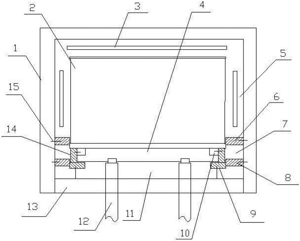
[0014] Embodiment 1, with reference to figure 1 , a high crystal quality polysilicon ingot thermal field, comprising an incubator 1 and a crucible 2 arranged in the furnace body, the crucible 2 is arranged in the incubator 1, the bottom of the incubator 1 is provided with an opening, and the bottom opening of the incubator is provided with There is a movable bottom plate 13, a heating device 3 is arranged in the incubator 1, a support mechanism for the crucible 2 is arranged on the movable bottom plate 13 of the incubator 1, and a thermal field is arranged in the incubator 1 above, below and around the crucible 2, so The heat field is divided into an upper heat field area 5, a middle heat field area 7, and a lower heat field area 11 through a multi-layer heat insulation mechanism, and the support mechanism includes a directional condensation plate 4 for placing the crucible 2 and a supporting directional condensation plate 4 The vertical struts 12 are installed in the furnace ...

Embodiment 2

[0016] Embodiment 2, the high crystal quality polysilicon ingot heat field described in embodiment 1 is provided with a circle of heat insulation wrapping around the outer periphery of the directional condensation plate 4; The movable insulating partition 14 opposite to the plate 8 is overlapped on the directional condensing plate 4 through the graphite block 10; a step matched with the graphite block 10 is provided on the top edge of the directional condensing plate 4.

Embodiment 3

[0017] Embodiment 3, the high crystal quality polysilicon ingot thermal field described in embodiment 1-2, is provided with a circle of motion insulation partitions 9 at the bottom of the directional condensation block 4, and the motion insulation partitions 9 are installed by carbon-carbon components 15 On the movable bottom plate, there is a heat transfer gap between the moving insulation partition 9 and the directional condensation block 4, and the gap rate is 50%-80%. The ratio of the gap between the plates to the total gap between the bottom of the crucible and the movable floor.


PUM


Abstract

The invention discloses a high crystal quality polysilicon ingot thermal field which comprises an insulated box and a crucible arranged in a furnace body, wherein the crucible is arranged in the insulated box; an opening is formed in the bottom of the insulated box; a movable bottom plate is arranged at the bottom opening of the insulated box; a heating device is arranged in the insulated box; a crucible supporting mechanism is arranged on the movable bottom plate of the insulated box; thermal fields are formed above and below the crucible and in the insulated box at the periphery; and three upper, middle and lower thermal field zones are separated in the thermal fields by virtue of a multilayer thermal insulation mechanism. Due to the multilayer thermal insulation mechanism, thermal field zone division is performed in the polysilicon ingot thermal field, different temperature zones are formed to perform layered control on the thermal flow, three temperature zone environments are formed from top to bottom, the thermal flow and temperature control in the polysilicon ingot smelting and crystallizing process can be achieved, and the controllability of a vertical temperature gradient in the insulated box is improved. Meanwhile, the transverse temperature consistency is ensured, and good thermal field distribution is formed.

Description

technical field [0001] The invention relates to a thermal field of a photovoltaic solar cell polycrystalline ingot, in particular to a thermal field of a polycrystalline silicon ingot with high crystal quality. Background technique [0002] Polycrystalline ingot casting is a key link in the current solar photovoltaic cell industry, which has a key impact on the quality of the final product cell. The photoelectric conversion efficiency of cells made of high-quality crystal quality polycrystalline silicon ingots is improved and the attenuation is reduced; it plays an important role in reducing overall costs and end-use effects, and the thermal field structure of polycrystalline silicon furnaces plays a decisive role in casting high-quality polycrystalline silicon ingots effect. At present, the thermal field of polycrystalline ingot usually does not carry out regionalized heat flow control in the thermal field. The initial, middle, and final stages of the crystallization proc...

Claims


Application Information

Patent Timeline
IPC IPC(8): C30B28/06C30B29/06
CPCC30B28/06C30B29/06
Inventor 张志强杨智兵卫巍
Owner HANWHA SOLARONE
Why Eureka
Try Eureka