
Automatic detection and performance analysis optimization device and system for optical system

An automatic detection and optical system technology, applied in the direction of testing optical performance, optical instrument testing, machine/structural component testing, etc., can solve problems such as increased difficulty, reduced efficiency, long adjustment time, etc., to reduce costs and risks, improve Effects of adjusting efficiency and improving utilization efficiency

Active Publication Date: 2017-05-24
大连鉴影光学科技有限公司
View PDF6 Cites 3 Cited by
  • Summary
  • Abstract
  • Description
  • Claims
  • Application Information

AI Technical Summary

Problems solved by technology

[0005] In the field of dish concentrating light, a blind adjustment method is often used, that is, to adjust to the sun so that each focused spot enters the concentrating hole; the main disadvantages of ordinary non-detection blind adjustment include: The adjustment amount is completely an estimated adjustment state, resulting in long adjustment time, low efficiency, and the adjustment effect and quality cannot be evaluated
Its main disadvantages: First, the actual condenser area is large, and the error distribution is uneven. Using a few points to describe its adjustment angle is likely to cause error deviation, resulting in a decline in the adjustment quality; less, it is impossible to fit the actual optical performance parameters, and it is impossible to theoretically give optical analysis
[0007] In this case, more enterprises use materials with better thermal conductivity and heat resistance at the receiving end, expand the receiving area, and speed up the fluidity of the introduced medium to solve the problem of unstable light-gathering performance. Fundamentally solve the problem and replace better materials, which directly leads to an increase in cost, but it cannot be guaranteed to be completely solved; in addition, expanding the area and speeding up the flow method reduces the collection temperature of the heat-absorbing gas end, which directly results in efficiency. The reduction of the cost of the new energy field has increased the difficulty of its development

Method used


Image

  • Automatic detection and performance analysis optimization device and system for optical system
  • Automatic detection and performance analysis optimization device and system for optical system
  • Automatic detection and performance analysis optimization device and system for optical system

Examples


Embodiment Construction

[0031]In order to make the technical problems solved by the present invention, the technical solutions adopted and the technical effects achieved clearer, the present invention will be further described in detail below in conjunction with the accompanying drawings and embodiments. It should be understood that the specific embodiments described here are only used to explain the present invention, but not to limit the present invention. In addition, it should be noted that, for the convenience of description, only parts related to the present invention are shown in the drawings but not all content.

[0032] 1. Structure and principle

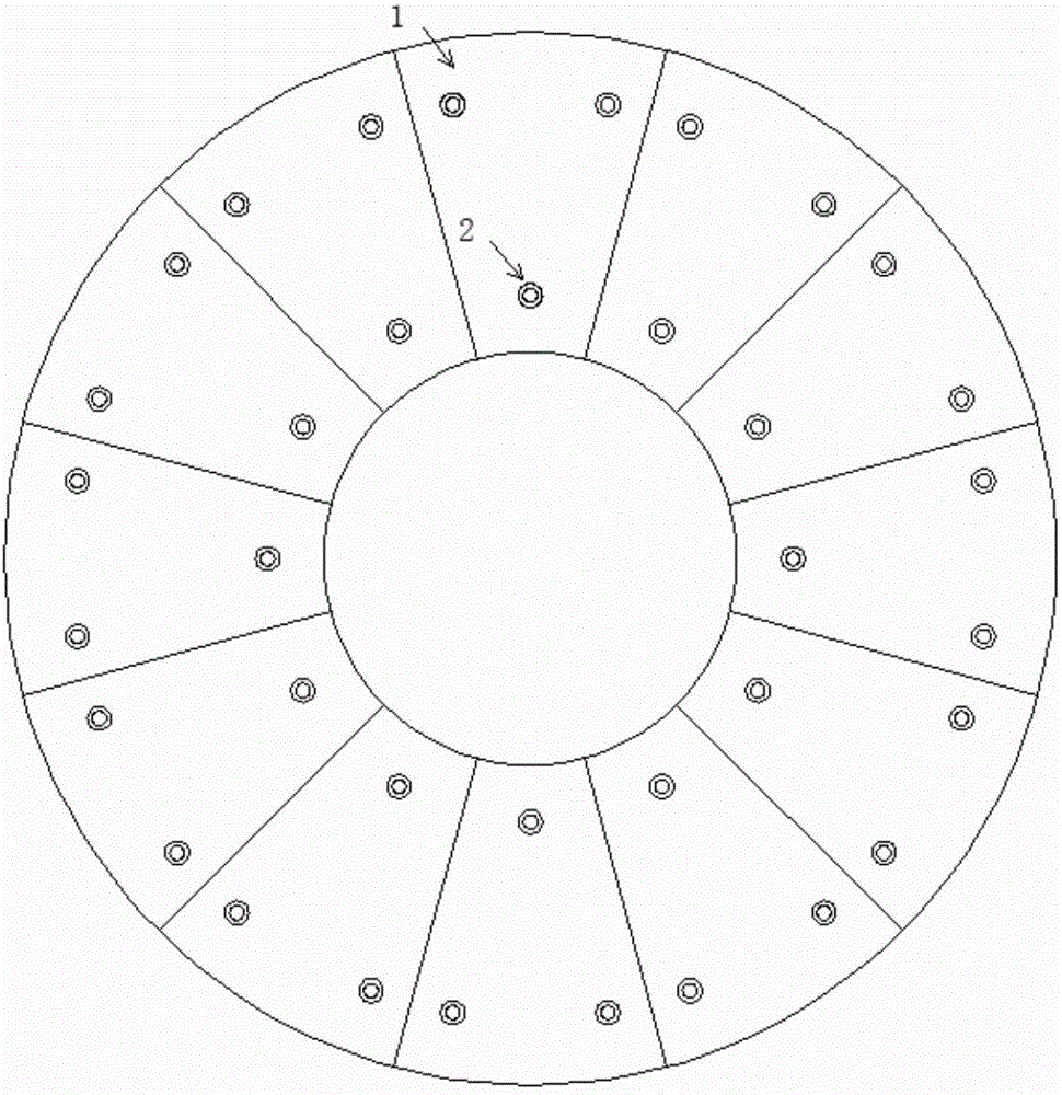
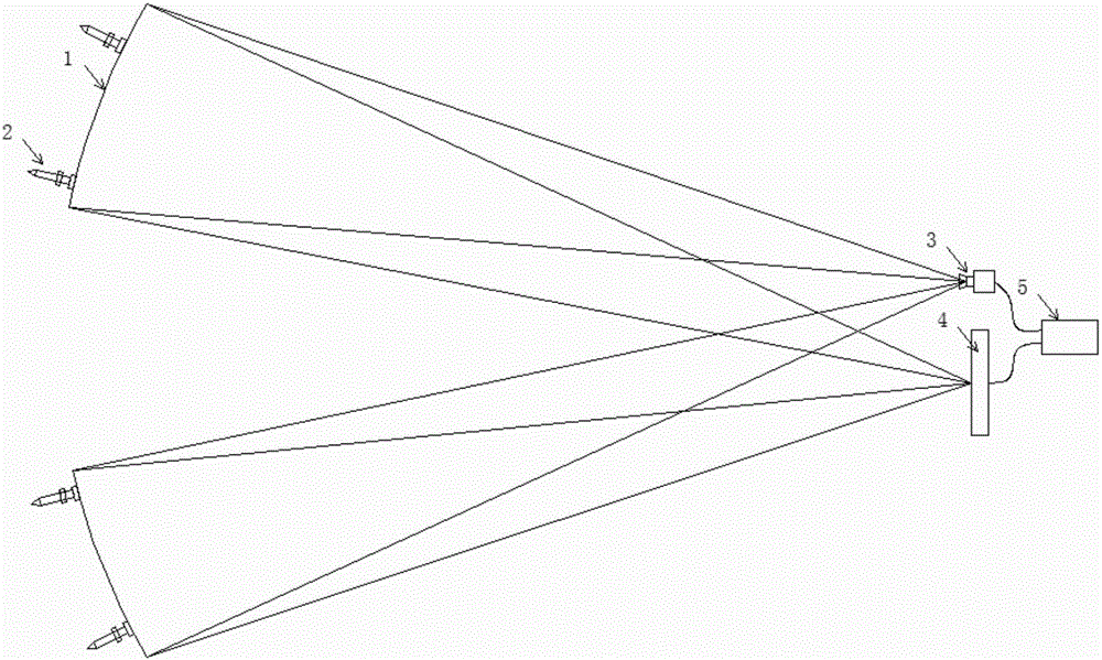
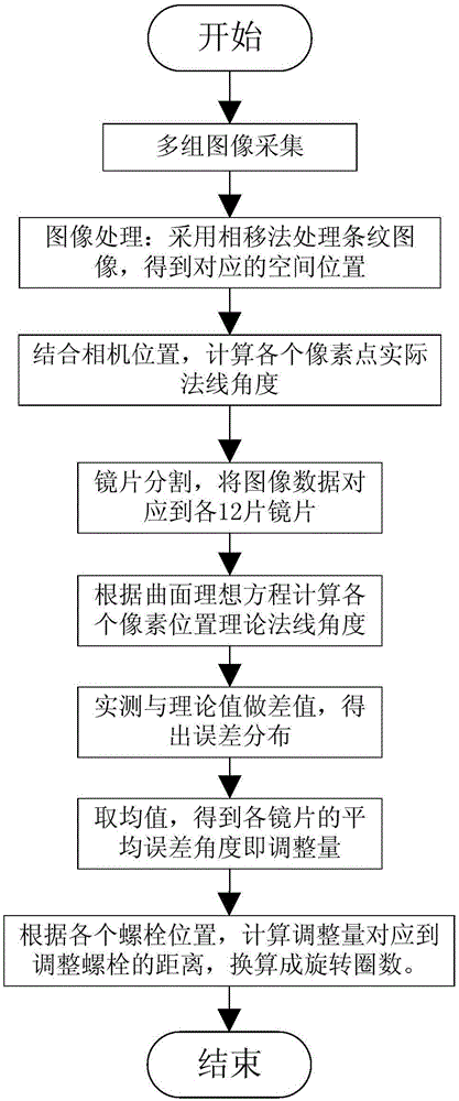
[0033] Please refer to figure 1 and figure 2 , the hardware structure of the automatic detection detection and performance analysis optimization equipment of the optical system of the present embodiment is: place image collector 3 and image display device 4 (this embodiment is flat plate TV), and be equipped with industrial computer 5 to conne...


PUM


Abstract

The invention discloses an automatic detection and performance analysis optimization device for an optical system. The device obtains the number of error points at the level of pixels in a mode of continuously changing images through image display equipment, cooperating with an image collector for collection and carrying out the processing of images, carries out the adjustment of a focusing system, the performance analysis, focusing light spot fitting and the evaluation of hot spot analysis, and finally obtains the optical system which accords with the expectation. The device and method improve the efficiency, and reduce the cost and risk. Because the image processing and analysis speed is high, the adjustment parameters of the whole optical system can be obtained in several seconds, and are used for guiding the manual or automatic adjustment equipment to carry out the adjustment, thereby greatly improving the adjustment efficiency, and reducing the adjustment cost and risks. Meanwhile, the device achieves the optical performance analysis and detection which accords with the reality. The device achieves the reverse performance optimization and improves the utilization efficiency.

Description

technical field [0001] The invention relates to the technical field of image detection and analysis, in particular to an automatic detection and performance analysis and optimization device and method for an optical system. Background technique [0002] In the field of solar thermal utilization, such as trough, tower, Fresnel and dish power generation, it involves the debugging and performance analysis of various optical lenses. A good optical lens field can not only improve power generation efficiency, but also Improve the stability of power generation. [0003] Taking the disc type as an example, a 4-cylinder Stirling engine is usually used in the front end of the power generation field. The Stirling generator has high requirements on the uniformity of the heated part. Low power generation efficiency. The side effect of the reduction in efficiency is that the accumulated heat cannot be converted and conducted away in time, resulting in heat accumulation and local overhea...

Claims


Application Information

Patent Timeline
Patent Type & Authority Applications(China)
IPC IPC(8): G01M11/02
CPCG01M11/0207G01M11/0257
Inventor 郭右利付瑶
Owner 大连鉴影光学科技有限公司
Learn More