
Thermal resistance detection method based on body diode

A detection method and thermal resistance technology, which is applied in the direction of single semiconductor device testing, measuring electricity, and measuring devices, can solve the problems of low thermal resistance detection efficiency and accuracy, and achieve improved detection sensitivity, simple steps, and easy test conditions Effect

Inactive Publication Date: 2017-05-24
宁波央腾汽车电子有限公司
View PDF3 Cites 2 Cited by
  • Summary
  • Abstract
  • Description
  • Claims
  • Application Information

AI Technical Summary

Problems solved by technology

[0004] Aiming at the problems of low thermal resistance detection efficiency and accuracy in the prior art mentioned above, a thermal resistance detection method aimed at improving detection accuracy and detection efficiency is now provided

Method used


Image

  • Thermal resistance detection method based on body diode
  • Thermal resistance detection method based on body diode
  • Thermal resistance detection method based on body diode

Examples


Embodiment Construction

[0023] The following will clearly and completely describe the technical solutions in the embodiments of the present invention with reference to the accompanying drawings in the embodiments of the present invention. Obviously, the described embodiments are only some, not all, embodiments of the present invention. Based on the embodiments of the present invention, all other embodiments obtained by persons of ordinary skill in the art without creative efforts fall within the protection scope of the present invention.

[0024] It should be noted that, in the case of no conflict, the embodiments of the present invention and the features in the embodiments can be combined with each other.

[0025] The present invention will be further described below in conjunction with the accompanying drawings and specific embodiments, but not as a limitation of the present invention.

[0026] A thermal resistance detection method, such as Figure 1-2 As shown, it is used to detect the thermal re...


PUM


Abstract

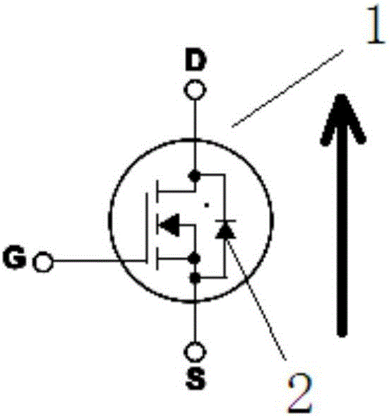
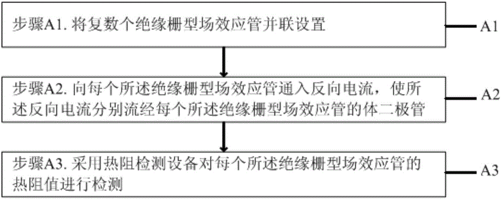
The invention provides a thermal resistance detection method based on a body diode, belongs to the technical field of electronic device detection, and is used for detecting the thermal resistance value of insulated gate field effect transistors. The insulated gate field effect transistors are enabled to work by a circuit. The method comprises the steps that the plural insulated gate field effect transistors are arranged in parallel; reverse current is piped into each insulated gate field effect transistor so that the reverse current is enabled to flow through the parasitic diode of each insulated gate field effect transistor; and the thermal resistance value of each insulated gate field effect transistor is detected by using thermal resistance detection equipment, wherein the reverse current is current inputted from the source electrode of each insulated gate field effect transistor and outputted from the drain electrode of each insulated gate field effect transistor. The beneficial effects of the thermal resistance detection method based on the body diode are that the current is piped into the parasitic diodes of a power MOS to test heat of each parallel branch MOS transistor to detect the thermal resistance value of the power MOS transistors and the thermal resistance uniformity so that the detection sensitivity can be enhanced, operation is easier and the cost is lower.

Description

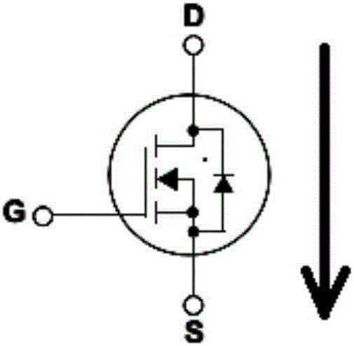
technical field [0001] The invention relates to the technical field of electronic device detection, in particular to a thermal resistance detection method based on a body diode. Background technique [0002] The motor controller with multiple tubes connected in parallel has strict requirements on the uniformity of the thermal resistance of each insulated gate field effect (Mosfet, MOS) tube, so a simple and effective method is needed to uniformly detect the thermal resistance. At present, the traditional detection method is to solder multiple MOS tubes in parallel on a printed circuit board (Printed Circuit Board, PCB), and pass forward current into each MOS tube, such as figure 1 , the current direction is shown by the arrow in the figure, the drain is the current input terminal, and the source is the current output terminal. A thermocouple (Negative Temperature Coefficient, NTC) is attached to each power MOS tube to detect the heat generation of each power MOS tube. By cal...

Claims


Application Information

Patent Timeline
Patent Type & Authority Applications(China)
IPC IPC(8): G01R31/26
CPCG01R31/2601G01R31/2628
Inventor 王迟
Owner 宁波央腾汽车电子有限公司
Learn More