Low-voltage micro-grid inverter control system based on virtual impedance and virtual power source

A technology of virtual power supply and virtual impedance, which is applied in the direction of electrical components, circuit devices, AC network circuits, etc., can solve problems such as increasing the deviation of reactive power sharing, incomplete power decoupling, and affecting the stable operation of the microgrid.

Active Publication Date: 2017-05-24
秦皇岛市睿能光电科技有限公司
View PDF7 Cites 27 Cited by
  • Summary
  • Abstract
  • Description
  • Claims
  • Application Information

AI Technical Summary

Problems solved by technology

The former can decouple the power to a certain extent by transforming the virtual coordinates of the power, but the stability of the microgrid is reduced
The latter makes the line impedance inductive by controlling the output impedance of the inverter, and then achieves the purpose of power decoupling. Generally, it can be divided into two categories. One is to take a virtual inductance with a larger value than the line impedance, so that the entire line Impedance is roughly inductive, but it increases the harmonic inductance of the system. At the same time, the existence of resistive line impedance will make the degree of power decoupling incomplete. The second...

Method used


Image

  • Low-voltage micro-grid inverter control system based on virtual impedance and virtual power source
  • Low-voltage micro-grid inverter control system based on virtual impedance and virtual power source
  • Low-voltage micro-grid inverter control system based on virtual impedance and virtual power source

Examples


Embodiment Construction

[0086] The present invention will be further described below in conjunction with accompanying drawing:

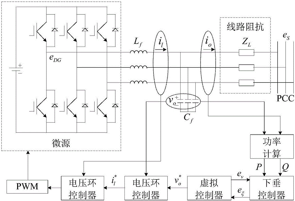
[0087] Micro-source control system of the present invention such as figure 1 As shown, the specific construction steps are as follows:

[0088] Step 1, determine the droop characteristic equation of the virtual power supply;

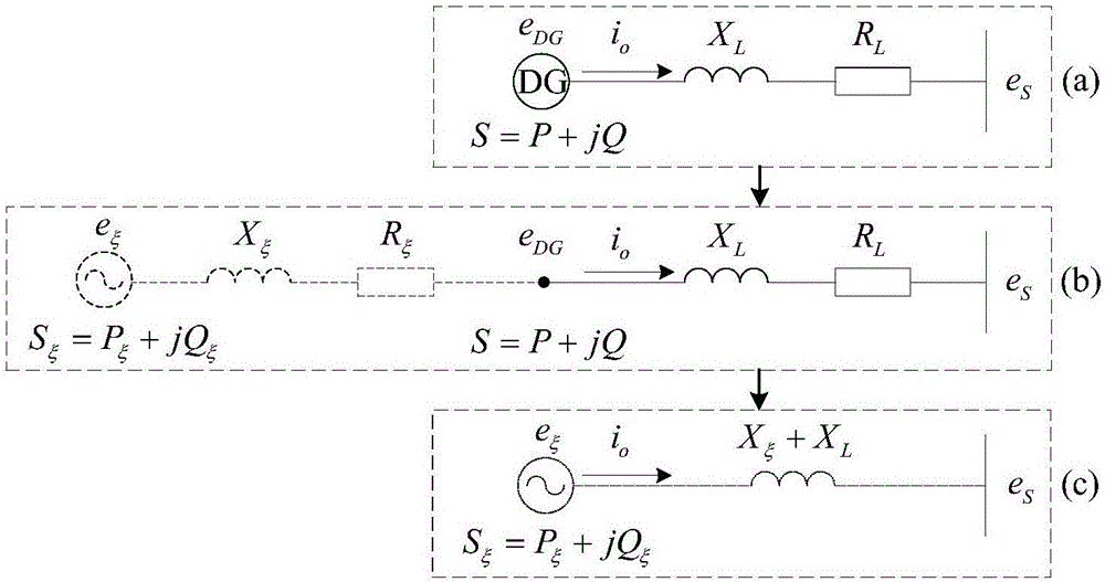
[0089] The principle structure diagram of the improved drooping system in the present invention is as follows: figure 2 shown, e ξ is the output voltage of the virtual power supply, e DG is the output voltage of the microsource, e S is the point of common coupling voltage, S ξ is the output power of the virtual power supply, S is the output power of the micro-source, R ξ is the virtual resistor, X ξ is the virtual inductance, R L is the line resistance, X L is the line inductance. The virtual negative resistance is used to offset the line resistance in the low-voltage micro-grid to decouple power, and the virtual negative inductance is used...


PUM


Abstract

The invention discloses a low-voltage micro-grid inverter control system based on virtual impedance and a virtual power source. The control system comprises a droop controller, a virtual controller and a voltage/current dual-loop controller, and is characterized by establishing the droop controller capable of simulating the function of the virtual power supply through improvement of droop parameters, and carrying out tracking control on the voltage of the droop controller through fractional-order PID; by analyzing relation between virtual negative inductance and micro-source reactive power sharing, determining the value of virtual negative inductance required for accurate reactive power sharing, realizing virtual impedance in the virtual controller, and feeding back voltage drop of the virtual controller to the droop controller to participate in fractional-order PID tracking control of voltage of the virtual power source; and carrying out tracking control on inverter voltage through fractional-order PID in the voltage/current dual-loop controller, determining filtering parameters in the controller according to a transfer function of a filter, and carrying out optimization on fractional-order PID controller parameters through a difference genetic algorithm. The control system can ensure low-voltage micro-grid power decoupling and improve a reactive power sharing effect.

Description

technical field [0001] The invention relates to the field of smart grid control, in particular to the design of an improved droop control method for a low-voltage micro-grid based on virtual impedance and virtual power supply and a complete control system thereof. Background technique [0002] With the continuous penetration of new energy and renewable energy power generation, in order to effectively solve many problems caused by the large-scale grid-connected state of distributed power generation and give full play to its potential, a micro-grid has been produced in the field of distributed power generation technology. The microgrid integrates various types of renewable energy such as photovoltaic power generation and wind power generation in the form of micro-sources, which improves the efficiency of resource use and better coordinates various micro-sources through cogeneration. As one of the control methods widely applicable to inverters in microgrids, the droop control m...

Claims


Application Information

Patent Timeline
IPC IPC(8): H02J3/38H02M7/537
CPCH02J3/382H02M7/537H02M1/0003
Inventor 窦春霞张占强岳东高含笑
Owner 秦皇岛市睿能光电科技有限公司
Why Eureka
Try Eureka