Control method of rectifier circuit switching tube of digital phase-shifting full-bridge DC converter
A technology of DC converter and full-bridge inverter circuit, which is applied in the direction of converting DC power input into DC power output, control/regulation system, and AC power input into DC power output, etc., which can solve low-voltage voltage fluctuation and output efficiency drop And other issues
- Summary
- Abstract
- Description
- Claims
- Application Information
AI Technical Summary
Problems solved by technology
Method used
Image
Examples
Embodiment 1
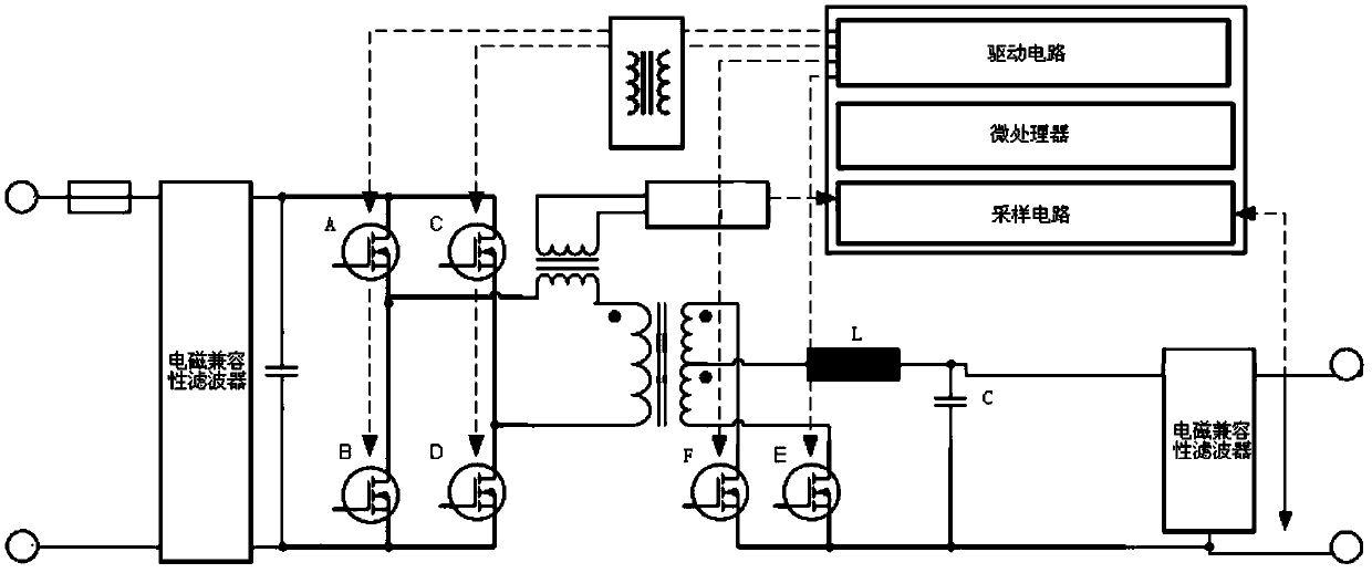
[0031] Digital phase-shifted full-bridge DC converters such as figure 1 As shown, its main circuit includes a full-bridge inverter circuit, a transformer, a rectifier circuit, and an LC filter circuit. The full-bridge inverter circuit on the high-voltage side of the primary side of the transformer includes four inverter switches (such as MOSFETs) A, B, C, D. The rectification circuit on the low-voltage side of the secondary side of the transformer includes two rectification switch tubes (such as MOSFETs) E, F.
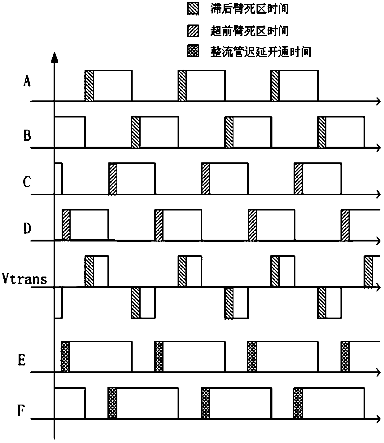
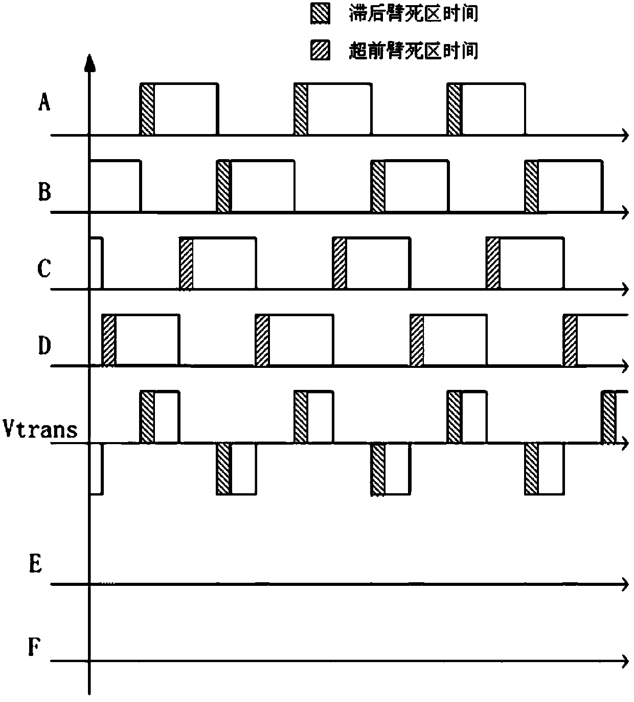
[0032] A rectification circuit switching tube control method for a digital phase-shifting full-bridge DC converter, such as Figure 7 shown, including the following steps:
[0033] 1. Collect the actual load current I of the phase-shifted full-bridge DC converter O ;
[0034] 2. If I O OB , proceed to step three, I OB is the critical load current;
[0035] 3. If I O >I off , I off To set the maximum shutdown current, proceed to step 4, otherwise proceed to ste...
Embodiment 2
[0044] Based on the digital phase-shift full-bridge DC converter control method of the rectifier circuit switching tube of the first embodiment, the critical load current I OB , can be determined by the following method:
[0045]
[0046] where V S is the bus voltage of the digital phase-shifting full-bridge DC converter (that is, the input voltage of the full-bridge inverter circuit), L is the inductance of the LC filter circuit (the nominal lower limit of the device can be taken), f S P is the switching frequency of the inverter switching tube, and P is the output duty ratio of the low-voltage side of the transformer. The output duty ratio P of the low-voltage side of the transformer can be set or calculated in real time.
[0047] The rectifier circuit switching tube control method of the digital phase-shifting full-bridge DC converter of the second embodiment, by collecting the bus voltage of the digital phase-shifting full-bridge DC converter, and combining the output...
Embodiment 3
[0049] Based on the rectifier circuit switching tube control method of the digital phase-shifting full-bridge DC converter of the second embodiment, the output duty ratio P of the low-voltage side of the transformer can be PI based on the difference between the measured voltage value of the low-voltage side of the transformer and the target value of the low-voltage voltage. (proportional-integral) control, or by performing PI control on the difference between the transformer low-voltage side current measurement value and the low-voltage current target value, such as Figure 8 shown.
PUM
 Abstract
Description
Claims
Application Information
 - R&D
- Intellectual Property
- Life Sciences
- Materials
- Tech Scout
- Unparalleled Data Quality
- Higher Quality Content
- 60% Fewer Hallucinations
Browse by: Latest US Patents, China's latest patents, Technical Efficacy Thesaurus, Application Domain, Technology Topic, Popular Technical Reports.
© 2025 PatSnap. All rights reserved.Legal|Privacy policy|Modern Slavery Act Transparency Statement|Sitemap|About US| Contact US: help@patsnap.com


