
A reference loop circuit with automatic input frequency identification function and its realization method

A technology for automatic identification and input of frequency, applied in automatic control of power, electrical components, etc., can solve problems such as inability to achieve frequency synchronization, and achieve the effects of simple and efficient implementation, low power consumption, and flexible and convenient programming

Active Publication Date: 2021-10-08
THE 41ST INST OF CHINA ELECTRONICS TECH GRP
View PDF4 Cites 0 Cited by
  • Summary
  • Abstract
  • Description
  • Claims
  • Application Information

AI Technical Summary

Problems solved by technology

In some test occasions, the signal to be tested is required to share a reference clock with the handheld spectrum analyzer in order to accurately test the frequency information of the signal. The synchronous reference clock frequency between the two is usually 10MHz. In some test occasions, such as The reference clock frequency in the communication room is 1.544MHz (T1) or 2.048MHz (E1). At this time, since the reference loop of the spectrum analyzer does not provide the relevant frequency interface, the frequency synchronization between the signal under test and the spectrum analyzer cannot be achieved.

Method used


Image

  • A reference loop circuit with automatic input frequency identification function and its realization method

Examples


Embodiment Construction

[0022] Below in conjunction with accompanying drawing and specific embodiment the present invention is described in further detail:

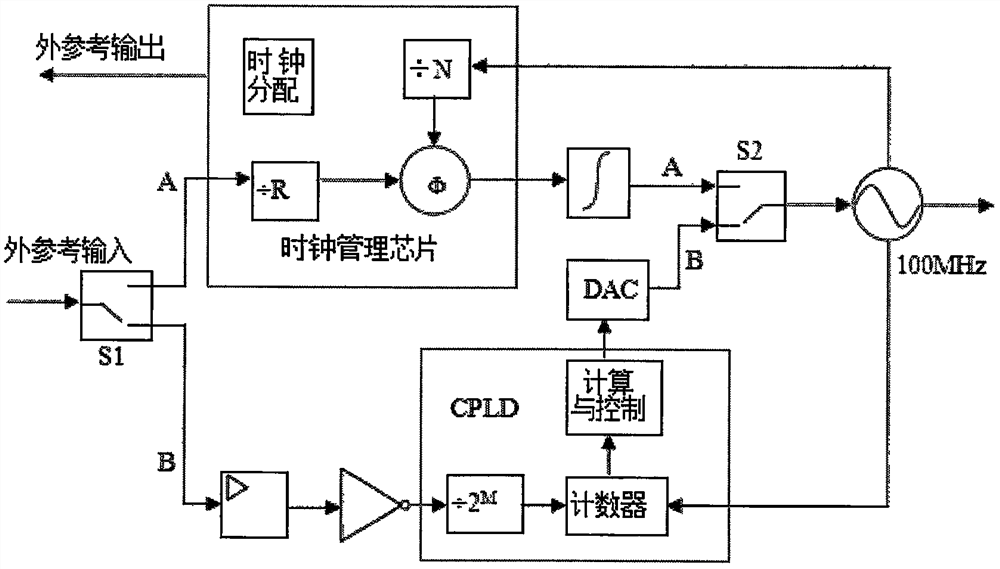
[0023] In this embodiment, a reference loop circuit with automatic input frequency identification function proposed by the present invention includes: switch S1, switch S2, clock management chip, loop filter, 100MHz crystal oscillator, limiting amplifier, inverter, CPLD and the DAC, the clock management chip and the loop filter are connected in series in sequence, the limiting amplifier, the inverter, the CPLD, and the digital-to-analog converter (DAC) are connected in series in sequence, and one end of the switch S1 is connected to the clock management chip and the limiter respectively. amplitude amplifier, one end of the switch S2 is respectively connected to the loop filter and the digital-to-analog converter, and the other end is connected to the 100MHz crystal oscillator.

[0024] The 100MHz crystal oscillator is a constant temperature crys...


PUM


Abstract

The invention relates to a reference loop circuit with automatic input frequency identification function and its realization method, comprising: CPLD-based input reference frequency automatic identification technology, counting the 100MHz crystal oscillator clock to be tuned after frequency division of the reference input frequency, counting The value is compared with the preset value in the program to determine the frequency value of the input reference signal. When it is determined that the reference frequency is an integer multiple of 1MHz, the CPLD controls the reference loop to perform phase-locked operation. When it is determined that the reference loop frequency is a non-integer multiple of 1MHz, the CPLD Control the DAC to adjust the frequency of the 100MHz crystal oscillator, so that the counting error is within the range of ±1, complete the frequency locking of the loop, and display the frequency value of the input external reference on the host interface. The invention realizes the automatic recognition of the external reference input frequency through the counting function of the CPLD, determines the external reference frequency value by the software and automatically performs the phase-locking or frequency-locking function, has the advantages of simple circuit design, flexible and convenient programming, and can identify any reference frequency value, circuit Small size, low power consumption and other advantages.

Description

technical field [0001] The invention relates to the technical field of electromagnetic wave energy testing, in particular to a reference loop circuit with an input frequency automatic identification function and a realization method. Background technique [0002] With the development of microwave integrated circuits and digital chip technology, the operating frequency band of handheld spectrum analyzers is getting higher and higher, the volume is smaller than previous products, the weight is lighter, and the functional indicators are more powerful. At present, handheld spectrum analyzers are widely used. It is widely used in the fields of wireless communication equipment installation and debugging, interference signal analysis, on-site maintenance of national defense and military equipment, and laboratory general spectrum measurement. In some test occasions, the signal to be tested is required to share a reference clock with the handheld spectrum analyzer in order to accurat...

Claims


Application Information

Patent Timeline
Patent Type & Authority Patents(China)
IPC IPC(8): H03L7/18
CPCH03L7/18
Inventor 李柏林肖江涛王健丁朋
Owner THE 41ST INST OF CHINA ELECTRONICS TECH GRP
Learn More