Plate warm electro-hydraulic high-speed impact-quasi static hydraulic composite forming device and plate forming method achieved by adopting device

A high-speed impact, composite forming technology, used in forming tools, metal processing equipment, manufacturing tools, etc., can solve problems such as uneven deformation, poor film bonding, difficult-to-form plates and complex parts forming, to prevent cracking and shorten forming. cycle, the effect of ensuring forming quality

Inactive Publication Date: 2017-05-31
XIANGTAN UNIV
View PDF5 Cites 18 Cited by
  • Summary
  • Abstract
  • Description
  • Claims
  • Application Information

AI Technical Summary

Problems solved by technology

[0005] The invention aims to solve the problems of difficult-to-form

Method used


Image

  • Plate warm electro-hydraulic high-speed impact-quasi static hydraulic composite forming device and plate forming method achieved by adopting device
  • Plate warm electro-hydraulic high-speed impact-quasi static hydraulic composite forming device and plate forming method achieved by adopting device
  • Plate warm electro-hydraulic high-speed impact-quasi static hydraulic composite forming device and plate forming method achieved by adopting device

Examples


specific Embodiment approach 1

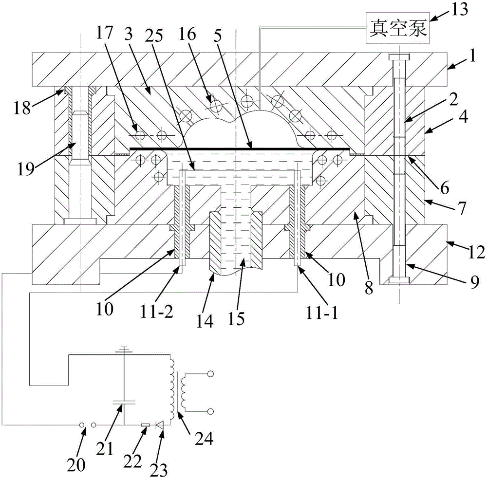
[0047] Specific implementation mode one: refer to Figure 1 to Figure 13 Describe this embodiment in detail. The plate warming electro-hydraulic high-speed impact-quasi-static hydraulic composite forming device described in this embodiment includes an electromagnetic forming system, a liquid filling device 14, an electro-hydraulic forming mold, a cooling device 16, and a heating device 17 and vacuum pump 13,

[0048] The electro-hydraulic forming mold includes an upper mold and a lower mold,

[0049] The upper part of the mold includes the upper mold seat plate 1, the No. 1 hexagon socket head screw 2, the concave mold cavity 3, the upper mold cover plate 4 and the guide sleeve 18,

[0050] The lower part of the mold includes the lower mold seat plate 12, the liquid chamber 8, the second hexagon socket screw 9, two insulating sleeves 10, the guide post 19, the lower mold cover plate 7, the discharge positive electrode 11-1, and the discharge negative electrode 11-2 and wire ...

specific Embodiment approach 2

[0061] Specific embodiment 2: This embodiment is a further description of the thermal electro-hydraulic high-speed impact-quasi-static hydraulic composite forming device described in specific embodiment 1. In this embodiment, it also includes a sealing ring 6, a concave mold cavity A sealing ring 6 is arranged between the cavity 3 and the liquid chamber 8, and the sealing ring 6 is used to provide a sealing effect for the cooperation between the concave mold cavity 3 and the liquid chamber 8.

[0062] In this embodiment, the sealing ring 6 between the concave mold cavity 3 and the liquid chamber 8 provides a sealing effect, and by changing and adjusting the thickness and elasticity of the sealing ring 6, the concave mold cavity 3 can be changed under the condition of providing a certain clamping force. The blank holder force of the plate 5 to be formed is used to achieve the purpose of improving the forming quality.

specific Embodiment approach 3

[0063] Specific embodiment 3: This embodiment is to further explain the thermal electro-hydraulic high-speed impact-quasi-static hydraulic composite forming device described in specific embodiment 1. In this embodiment, the diameter of the metal wire 25 is 0.6 mm to 1.6 mm. mm, the length of the wire 25 is consistent with the groove length of the concave mold cavity 3, and the wire 25 remains parallel to the plate 5 to be processed.


PUM

PropertyMeasurementUnit
Diameteraaaaaaaaaa

Abstract

The invention discloses a plate warm electro-hydraulic high-speed impact-quasi static hydraulic composite forming device and a plate forming method achieved by adopting the device and relates to the field of metal material processing forming to solve the problems that forming of plates and complex parts is difficult, film attaching is poor, and deformation is not even. A vacuum pump is used for pumping out gas in a female die cavity; a fluid injection device is adopted for injecting high-temperature-resisting liquid to a liquid chamber; a heating device is used for heating the female die cavity, the high-temperature-resisting liquid in the liquid chamber is heated, preheating on a to-be-processed plate is completed, and heat preservation is conducted on the to-be-processed plate; an electromagnetic forming system is used for conducting discharging forming on the to-be-processed plate; high-pressure warm liquid is slowly injected into the liquid chamber under the quasi static condition, and quasi static hydraulic forming is conducted on the to-be-processed plate; and the high-pressure warm liquid in the liquid chamber is cooled to the room temperature within a period of time, waste liquid is recycled, an electro-hydraulic forming die is opened, and the to-be-processed plate is taken away. The device and the method are used for forming plates.

Description

technical field [0001] The invention relates to a plate warming, electro-hydraulic high-speed impact-quasi-static hydraulic composite forming device and a plate forming method realized by the device. It belongs to the field of metal material processing and forming. Background technique [0002] With the advancement of science and technology and the improvement of people's living standards, sheet metal forming parts are more and more widely used in people's lives. The forming of the plate usually adopts the stamping method. The traditional stamping method requires the design of a special mold. Not only the mold structure is complex, the design cycle is long, and the manufacturing cost is high. More importantly, the punch and the die need to be precisely matched and positioned. , Also consider the wear and fit tolerance of the male and female dies, as well as the hardening of the material during the stamping forming process, which will cause an increase in deformation resista...

Claims


Application Information

Patent Timeline
IPC IPC(8): B21D26/14B21D26/021B21D37/16B21D26/031B21D37/10
CPCB21D26/021B21D26/031B21D26/14B21D37/10B21D37/16
Inventor 徐俊瑞文智生崔俊佳张旭谢雪云封元华
Owner XIANGTAN UNIV
Why Eureka
Try Eureka