
Coaxial visual cutting device used for glass cutting

A technology of visual tracking and cutting device, applied in laser welding equipment, manufacturing tools, welding equipment and other directions, can solve the problems of increasing the purchase of raw materials, increasing production costs, cutting errors, etc., to reduce processing costs, solve inefficiency, and improve finished products. rate effect

Inactive Publication Date: 2017-05-31
SUZHOU DADAO LASER APPL TECH CO LTD
View PDF7 Cites 3 Cited by
  • Summary
  • Abstract
  • Description
  • Claims
  • Application Information

AI Technical Summary

Problems solved by technology

[0003] In electronic products, glass is used as screens, display screens, etc. Usually, when processing screens, a glass cutting machine is used to cut large pieces of glass and then perform a post-cutting process to process the glass. The existing glass cutting machine Using mechanical cutting or laser cutting, the weakness of mechanical cutting is that it is easy to damage the glass during the cutting process, the yield rate is low, and there are many defective products, which increases the purchase of raw materials and increases the production cost; the weakness of laser cutting is that it cannot be accurately cut lines and cutting points, it is easy to cause cutting errors and waste materials

Method used


Image

  • Coaxial visual cutting device used for glass cutting
  • Coaxial visual cutting device used for glass cutting

Examples


Embodiment Construction

[0014] In order to make the technical means, creative features, goals and effects achieved by the present invention easy to understand, the present invention will be further described below in conjunction with specific embodiments.

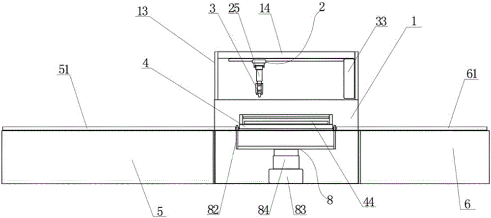
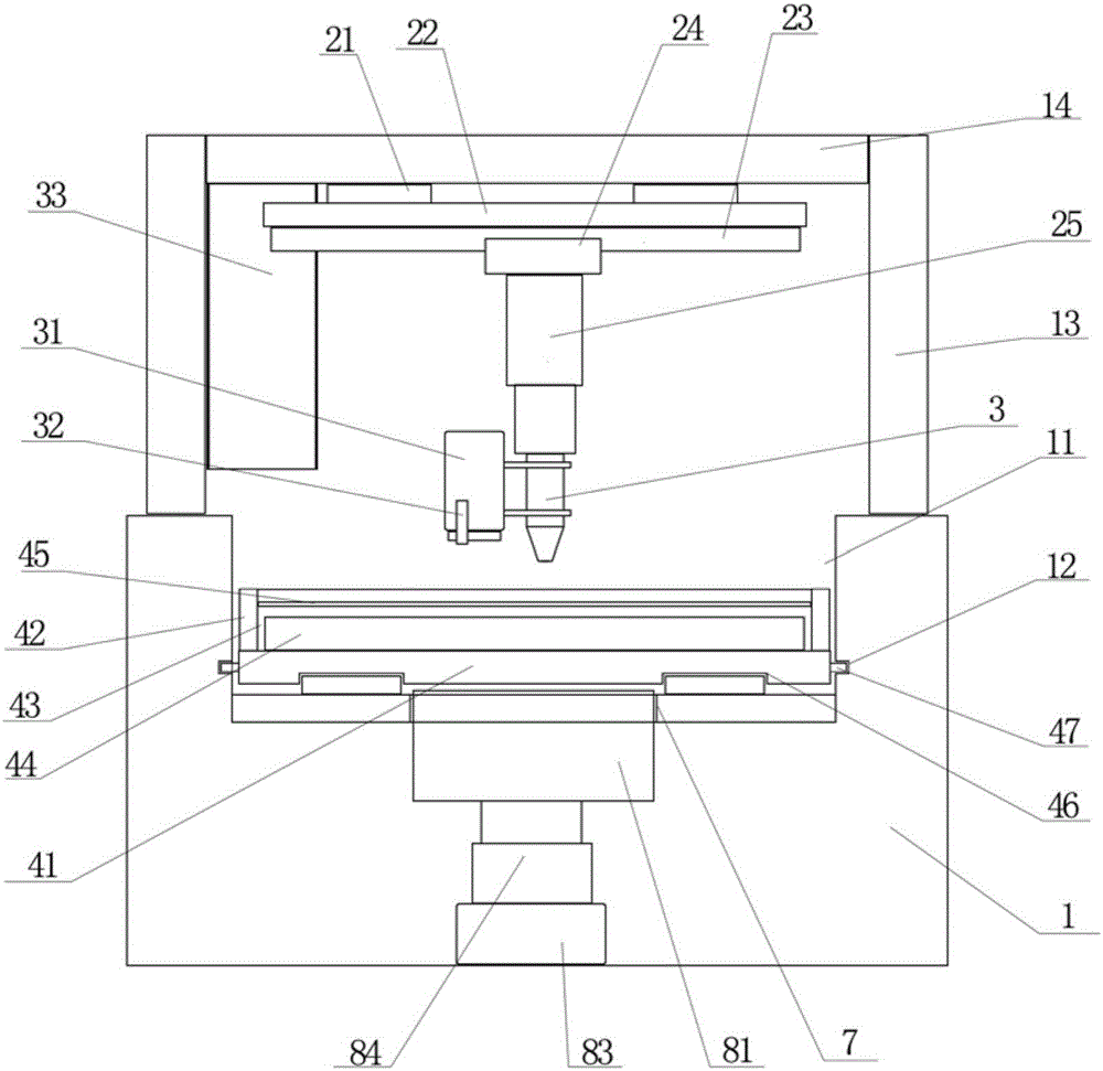
[0015] Such as figure 1 with figure 2 As shown, a coaxial visual tracking cutting device for glass cutting of the present invention includes a frame 1 and a first bracket 5 and a second bracket 6 respectively arranged at both ends of the frame 1, and is characterized in that: The top of the frame 1 is provided with a cutting station slot 11 downwards, and the top of the first support 5 is provided with a slideway assembly, which extends in the cutting station slot 11, and the slideway assembly includes two horizontally arranged guide rails 51. The track assembly is provided with a cutting carrier 4 that can move with the slideway assembly. The top of the frame 1 is provided with a support frame 13. The top of the support frame 13 includes a top ...


PUM


Abstract

The invention discloses a coaxial visual cutting device used for glass cutting. The coaxial visual cutting device comprises a rack as well as a first bracket and a second bracket which are separately arranged at the two ends of the rack, wherein the top of the rack is downwards equipped with a cutting station slot; the top of the first bracket is equipped with a slide path assembly; the slide path assembly extends into the cutting station slot; a cutting carrier is arranged on the slide path assembly; a supporting frame is arranged on the top of the rack; the top of the supporting frame comprises a top plate; a cutting assembly is arranged on the top plate; the cutting assembly comprises two first slide rails which are horizontally arranged on the bottom of the top plate; a movable plate is arranged on the two first slide rails; the bottom of the movable plate is horizontally equipped with a second slide rail; a slide plate is arranged on the second slide rail; the bottom of the slide plate is equipped with a telescopic pole; the bottom end of the telescopic pole is connected with a laser cutter; one side of the laser cutter is connected with a CCD camera; the side surface of the supporting frame is equipped with a main controller; and the main controller is connected with the CCD camera.

Description

technical field [0001] The invention relates to the technical field of glass cutting, in particular to a coaxial visual tracking cutting device for glass cutting. Background technique [0002] Glass is formed by melting sand and other chemicals together. A silicate-based non-metallic material that forms a continuous network structure during melting, and gradually increases in viscosity and hardens during cooling to cause it to crystallize. At present, glass is widely used in various fields of life, such as construction, electronic products and so on. [0003] In electronic products, glass is used as screens, display screens, etc. Usually, when processing screens, a glass cutting machine is used to cut large pieces of glass and then perform a post-cutting process to process the glass. The existing glass cutting machine Using mechanical cutting or laser cutting, the weakness of mechanical cutting is that it is easy to damage the glass during the cutting process, the yield ra...

Claims


Application Information

Patent Timeline
Patent Type & Authority Applications(China)
IPC IPC(8): B23K26/042B23K26/08B23K26/38
CPCB23K26/042B23K26/0869B23K26/38B23K2103/54
Inventor 李有盛
Owner SUZHOU DADAO LASER APPL TECH CO LTD
Learn More