Hydraulic supporting clamp for rotor processing

A hydraulic support and rotor technology, which is applied in the direction of manufacturing tools, workpiece clamping devices, metal processing equipment, etc., can solve the problems of long assembly and disassembly preparation period, complex process realization, and difficulty in fixing processing equipment, etc., to achieve design and manufacturing The effect of short cycle, low cost and simple structure

Inactive Publication Date: 2017-05-31
SHENYANG LIMING AERO-ENGINE GROUP CORPORATION
View PDF5 Cites 4 Cited by
  • Summary
  • Abstract
  • Description
  • Claims
  • Application Information

AI Technical Summary

Problems solved by technology

[0002] A certain size of the high-pressure turbine rotor of an engine requires component processing. The transfer tooling fit between the parts and the machine tool is an interference fit. The traditional tooling design needs to cool or heat the parts before assembling. After assembly, the room temperature needs to be restored, which has a long assembly cycle and waste of energy
[0003] The rear shaft structure of the high-vortex rotor is an internal support structure, and the support reference is located in the inner cavity of the rear shaft. It is not a general outer circular clamping structure, and it is difficult to fix it on the processing equipment. Therefore, a special support fixture is proposed, and the rear shaft inner cavity is used as the positioning reference. However, due to the positioning and assembly relationship between the fixture and the inner cavity of the rear axle, an interference fit is required. In addition to the long assembly and disassembly preparation period, the general cold and hot assembly fixtures also require special heating or cooling solutions and special disassembly process equipment. Increased requirements, etc., the process is complex and difficult

Method used


Image

  • Hydraulic supporting clamp for rotor processing

Examples


Embodiment 1

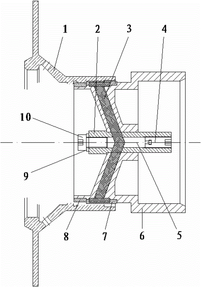
[0016] The hydraulic support fixture for rotor processing is composed as follows: bushing 2, liquid plastic 3, first screw 4, plunger 5, positioning sleeve 6, bushing 7, retaining sleeve 8, composite washer 9 and second screw 10; , the positioning sleeve 6 is a main structural part. The positioning sleeve 6 includes a small end ring and a large end ring. The support structure is matched, the outer groove of the small end ring supports the bushing 7, the bushing 7 is fixed on the small end ring of the positioning sleeve 6 through the stop sleeve 8, and the stop sleeve 8 is assembled to the small end of the positioning sleeve 6, after assembly Fix the bushing 7 on the positioning sleeve 6, and seal the groove cavity formed by the two pieces. The outer side of the bushing 7 and the inner hole of the rear shaft of the high-vortex rotor 1 are mating surfaces. The bushing 2 is assembled on the center of the positioning sleeve 6, and the inner hole of the bushing 2 is connected with ...


PUM


Abstract

The invention discloses a hydraulic supporting clamp for rotor processing. The hydraulic supporting clamp for rotor processing comprises a liner (2), liquid plastic (3), a first screw (4), a plunger (5), a positioning sleeve (6), a liner (7), a retaining sleeve (8), a composite cushion ring (9) and a second screw (10), wherein the positioning sleeve (6) is a main body structure part and is composed of a small end ring and a large end ring; the small end ring and the large end ring are coaxially integrated; the inner side of the large end ring is matched with a processing equipment supporting structure; and an outer side groove of the small end ring supports the liner (7). The hydraulic supporting clamp for rotor processing is simple in structure, high in practicability, short in design and manufacturing period, low in cost, convenient to use and easy to operate, can accurately position a machine element, lowers auxiliary cost brought by a conventional tool and improves the assembly efficiency.

Description

technical field [0001] The invention relates to the technical field of structural design and application of machining fixtures, and in particular provides a hydraulic support fixture for rotor machining. Background technique [0002] A certain size of the high-pressure turbine rotor of an engine requires component processing. The transfer tooling fit between the parts and the machine tool is an interference fit. The traditional tooling design needs to cool or heat the parts before assembling. After assembly, the room temperature needs to be restored, which has a long assembly cycle and waste of energy. [0003] The rear shaft structure of the high-vortex rotor is an internal support structure, and the support reference is located in the inner cavity of the rear shaft. It is not a general outer circular clamping structure, and it is difficult to fix it on the processing equipment. Therefore, a special support fixture is proposed, and the rear shaft inner cavity is used as the...

Claims


Application Information

Patent Timeline
Patent Type & Authority Applications(China)
IPC IPC(8): B23Q3/08B25B11/02
CPCB23Q3/082B25B11/02
Inventor 杜立峰王景秋林东孙逍遥张友辉
Owner SHENYANG LIMING AERO-ENGINE GROUP CORPORATION
Why Eureka
Try Eureka