Machining magnetic field shielding method and device for permanent magnet contained workpiece
A permanent magnet and machining technology, which is applied in shielding, metal processing equipment, metal processing machinery parts, etc., can solve the problems of undisclosed split-type shielding devices and methods, and improve precision and processing quality, disassembly and assembly Convenience, effect of avoiding looseness and vibration problems
- Summary
- Abstract
- Description
- Claims
- Application Information
AI Technical Summary
Problems solved by technology
Method used
Image

Examples
Embodiment 1
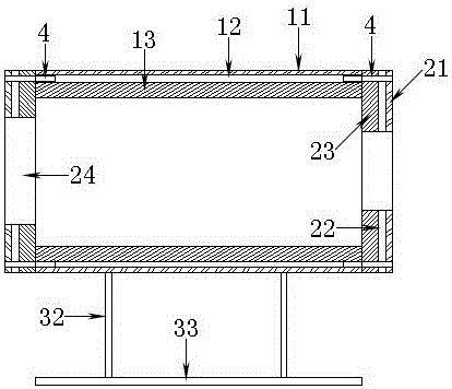
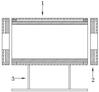
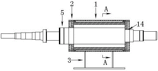
[0038] Such as figure 1 , figure 2 with image 3 As shown, the magnetic field shielding device includes a shielding cover 1 and an end cover 2, the shielding cover 1 includes a shielding cylinder 11, a rubber layer 12 and a silicon steel cylinder 13, and the end cover 2 includes a shielding cover 21, an end cover rubber layer 22, a silicon steel cover 23 and assembly Hole 24. Wherein the silicon steel cylinder 13 and the silicon steel cover 23 are formed by stacking a plurality of thin silicon steel sheets. The shielding cylinder 11 and the shielding cover 21 can be made of pure iron and low carbon steel, iron-silicon alloy, iron-aluminum alloy, iron-silicon-aluminum alloy, nickel-iron alloy, iron-cobalt alloy, soft ferrite, non It is made of magnetic materials such as crystalline soft magnetic alloy and ultrafine crystal soft magnetic alloy.
[0039]The silicon steel cylinder 13 and the shielding cylinder 11 are vulcanized into a whole through the rubber layer 12, and th...
Embodiment 2
[0049] The difference from Embodiment 1 is that the shielding cover 1 only includes the silicon steel cylinder 13 without the shielding cylinder 11, and the silicon steel sheets in the silicon steel cylinder 13 are passed through by a screw, and the two ends of the screw are tightened with nuts, so as to press Tight silicon steel sheet. The end cover 2 also only includes a silicon steel cover 23 without a shielding cover 21, and the silicon steel sheets in the silicon steel cover 23 are passed through by a screw, and are tightened with nuts at both ends of the screw. That is to say, the magnetic field shielding is performed only once on both the shielding case 1 and the end cap 2 . This embodiment can be applied to working conditions where the magnetic field strength generated by the permanent magnet workpiece 5 is not strong, and can save the manufacturing cost of the magnetic field shielding device.
Embodiment 3
[0051] The difference from Embodiment 1 is that neither the shielding case 1 nor the end cap 2 is a split structure, but the cross section of the shielding case 1 and the end cap 2 is a complete ring. And the shielding cover 1 and the end cover 2 are vulcanized into a whole, or welded into a whole. This embodiment can be applied in the working condition that one end of the permanent magnet processing part 5 is easy to disassemble. On the part 5, install one end of the permanent magnet processing part 5 and get final product.
PUM
 Abstract
Description
Claims
Application Information
 - R&D
- Intellectual Property
- Life Sciences
- Materials
- Tech Scout
- Unparalleled Data Quality
- Higher Quality Content
- 60% Fewer Hallucinations
Browse by: Latest US Patents, China's latest patents, Technical Efficacy Thesaurus, Application Domain, Technology Topic, Popular Technical Reports.
© 2025 PatSnap. All rights reserved.Legal|Privacy policy|Modern Slavery Act Transparency Statement|Sitemap|About US| Contact US: help@patsnap.com