Printed electronic printing device supporting flow line production and production system

An electronic printing and assembly line technology, applied in printed circuit, printed circuit manufacturing, printing, etc., can solve the problems of inconvenient clamping of workpieces, failure of assembly line production, and inability to clamp workpieces, etc., to achieve good product quality, realize automatic production, The effect of improving processing efficiency

Active Publication Date: 2017-05-31
江苏汉印机电科技股份有限公司
View PDF11 Cites 3 Cited by
  • Summary
  • Abstract
  • Description
  • Claims
  • Application Information

AI Technical Summary

Problems solved by technology

[0003] However, the existing printer is inconvenient to clamp the workpiece, and the workpiece cannot be clamped during the printing process of the printer, and cannot be produced in an assembly line, resulting in low production efficiency, high manufacturing cost, and high labor intensity.

Method used


Image

  • Printed electronic printing device supporting flow line production and production system
  • Printed electronic printing device supporting flow line production and production system
  • Printed electronic printing device supporting flow line production and production system

Examples


Embodiment 1

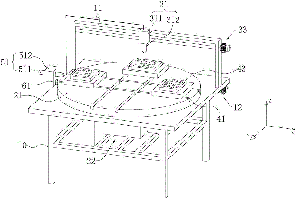
[0040] refer to figure 1 As shown, a printed electronic printing device supporting assembly line production provided by Embodiment 1 of the present invention includes a frame 10 , a jet printing device, a rotating device and a workbench 41 .

[0041] The frame 10 mainly plays the role of supporting other components, and the frame 10 can be made into a frame structure, for example, it can be made by welding rectangular tubes or angle steels. Of course, it can also be connected with bolts. The welded structure is solid and reliable, and the appearance is beautiful; the bolted connection is easy to disassemble and assemble.

[0042] It should be noted that, in this embodiment, the horizontal direction of the rack 10 is defined as the X direction, the longitudinal direction of the rack 10 is defined as the Y direction, and the vertical direction of the rack 10 is defined as the Z direction.

[0043] The rotating device is used to drive the workpiece to rotate, and the rotating d...

Embodiment 2

[0073] A production system provided by Embodiment 2 of the present invention includes a printed electronic printing device supporting assembly line production, hole processing equipment and cleaning equipment.

[0074] It should be noted that the printed electronic printing device supporting assembly line production can adopt the printed electronic printing device supporting assembly line production in Embodiment 1, and its structure, working principle and technical effects can refer to the corresponding content in Embodiment 1 , which will not be described in detail here.

[0075] Both hole processing equipment and cleaning equipment can be selected from existing equipment, or special equipment can be used.

[0076] The production system has high production efficiency, can realize automatic production, has low manufacturing cost, low labor intensity and good quality of produced products.


PUM


Abstract

The invention provides a printed electronic printing device supporting flow line production and a production system and belongs to the technical field of printed circuits. The printed electronic printing device supporting flow line production comprises a rack, a jet printing device, a rotating device and a worktable; the jet printing device comprises a jet head assembly which is supported on the rack through a portal frame, the jet head assembly is slidably connected with the portal frame, and a first driving mechanism is installed between the jet head assembly and the portal frame; the portal frame is slidably connected with the rack, and a second driving mechanism is installed between the portal frame and the rack; the rotating device comprises a rotating table and a third driving mechanism, the rotating table is rotatably connected with the rack, the third driving mechanism is fixed to the rack and connected with the rotating table, and the third rotating mechanism can drive the rotating table to rotate around the axis of the rotating table; and the worktable is slidably supported on the rotating table. The printed electronic printing device supporting flow line production is simple in structure and convenient to use. The production system is high in production efficiency, automatic production can be achieved, manufacturing cost is low, and labor intensity is low.

Description

technical field [0001] The invention relates to the technical field of printed circuits, in particular to a printed electronic printing device and a production system supporting assembly line production. Background technique [0002] With the development of science and technology, PCB has entered the era of Printed Electronics. Printed electronics can be made into complex electronic circuits combining electronic components and circuits through various printing technologies, so it is also called "printed electronic circuits". Among various printing technologies, inkjet printing technology is widely used to print electronic circuits. [0003] However, the existing printer is inconvenient to clamp the workpiece, and the workpiece cannot be clamped during the printing process of the printer, and cannot be produced in an assembly line, resulting in low production efficiency, high manufacturing cost, and high labor intensity. Contents of the invention [0004] The purpose of t...

Claims


Application Information

Patent Timeline
IPC IPC(8): B41J2/01B41J3/407
CPCH05K13/0469H05K3/125B41J2/01B41J3/407
Inventor 周临震文成金光涛陈国兰周薇宦海祥李青祝张侃楞
Owner 江苏汉印机电科技股份有限公司
Why Eureka
Try Eureka