Method for recycling sulfur through Claus direct-flow method
A direct current method, sulfur technology, applied in the field of sulfur recovery, Claus method to recover sulfur, to achieve the effect of improving the sulfur recovery rate, reducing the entry into the reactor, and saving costs
- Summary
- Abstract
- Description
- Claims
- Application Information
AI Technical Summary
Problems solved by technology
Method used
Image

Examples
Embodiment 1
[0034] A method for recovering sulfur by Claus DC method includes the following method steps:
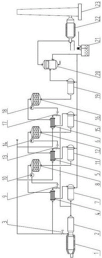
[0035] A. The combustion furnace is connected to the waste heat boiler, and the combustion furnace is connected to the high-temperature acid gas inlets of the first gas-gas heat exchanger, the second gas-gas heat exchanger and the third gas-gas heat exchanger through the high-temperature acid gas flow control valve The waste heat boiler is connected to the presulfur cooler; the high temperature acid gas in the combustion furnace enters the first gas heat exchanger, and the low temperature acid gas in the waste heat boiler enters the first gas heat exchanger through the presulfur cooler A gas-to-gas heat exchanger, where two acid gases in the first gas-to-gas heat exchanger perform gas-to-gas heat exchange;
[0036] B. The low-temperature acid gas outlet of the first gas-gas heat exchanger is connected to the first-stage reactor, and the high-temperature acid gas outlet of the first gas-g...
Embodiment 2
[0041] On the basis of Example 1:
[0042] Preferably, in step A, the temperature of the high-temperature acid gas in the combustion furnace is 1000°C.
[0043] Preferably, in step B, the temperature of the low-temperature acid gas in the waste heat boiler is 340°C, and the temperature of the low-temperature acid gas after passing through the presulfur cooler is 140°C.
[0044] Preferably, in step C, the temperature of the low-temperature acid gas entering the first-stage reactor is 280°C.
[0045] Preferably, in step D, the temperature of the low-temperature acid gas entering the secondary reactor is 250°C.
[0046] Preferably, in step E, the temperature of the low-temperature acid gas entering the three-stage reactor is 180°C.
Embodiment 3
[0048] On the basis of Example 1:
[0049] Preferably, in step A, the temperature of the high-temperature acid gas in the combustion furnace is 1200°C.
[0050] Preferably, in step B, the temperature of the low-temperature acid gas in the waste heat boiler is 350°C, and the temperature of the low-temperature acid gas after passing through the presulfur cooler is 160°C.
[0051] Preferably, in step C, the temperature of the low-temperature acid gas entering the first-stage reactor is 310°C.
[0052] Preferably, in step D, the temperature of the low-temperature acid gas entering the secondary reactor is 280°C.
[0053] Preferably, in step E, the temperature of the low-temperature acid gas entering the three-stage reactor is 200°C.
PUM
 Abstract
Description
Claims
Application Information
 - R&D
- Intellectual Property
- Life Sciences
- Materials
- Tech Scout
- Unparalleled Data Quality
- Higher Quality Content
- 60% Fewer Hallucinations
Browse by: Latest US Patents, China's latest patents, Technical Efficacy Thesaurus, Application Domain, Technology Topic, Popular Technical Reports.
© 2025 PatSnap. All rights reserved.Legal|Privacy policy|Modern Slavery Act Transparency Statement|Sitemap|About US| Contact US: help@patsnap.com