Ballastless track grouting lifting and lifting correcting method

A ballastless track, grouting lifting technology, applied in the direction of track, track laying, track maintenance, etc., can solve the problems of adjusting the height and level of the track, difficult to control the adjustment amount, limited adjustment amount, etc., to achieve displacement and displacement error. Precise control, saving grouting material, cost-effective effect

Inactive Publication Date: 2017-05-31
BEIJING RUIWEI TIEKE HIGH SPEED RAIL ENG CO LTD
View PDF5 Cites 24 Cited by
  • Summary
  • Abstract
  • Description
  • Claims
  • Application Information

AI Technical Summary

Problems solved by technology

Compared with the ballasted track structure, the integral structural characteristics of the ballastless track make it have significant advantages in maintaining the stability and smoothness of the track, but it limits the adjustable range of the ballastless track structure, that is, only in the fastener The system allows the smoothness of the track structure to be repaired within an adjustable range
Similarly, in engineering practice, due to factors such as special engineering geology, construction quality control, and changes in the external environment, the ballastless tracks of high-speed railways in some subgrade sections have local settlements during the construction stage or after operation and opening, resulting in track heights, horizontal Problems such as deviations that do not meet the static acceptance standards or exceed the adjustment range of fasten

Method used


Image

  • Ballastless track grouting lifting and lifting correcting method
  • Ballastless track grouting lifting and lifting correcting method
  • Ballastless track grouting lifting and lifting correcting method

Examples


Embodiment 1

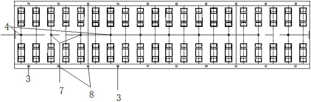
[0044] Attached below Figure 1-3 , to illustrate the CRTS II ballastless track grouting lifting method of the first embodiment of the present invention, the method includes the following:

[0045] (1) The layout position of grouting hole and filling hole, the lifting amount is determined

[0046]Before grouting, use a high-precision level and geological radar to detect the rail surface and the void area under the rail, compare it with the design elevation, check the control limit of subgrade settlement and deformation in relevant regulations, and determine the uplift position and uplift amount . Calculate the grouting hole diameter and layout spacing according to the actual situation on site. The diameter of grouting holes 3 and 4 and filling holes 7 and 8 should be 80mm, the spacing between filling holes should be 1.3m, and the spacing between grouting holes should be 3.9m , and the principle of arranging a grouting hole every two filling holes should be followed when dist...

Embodiment 2

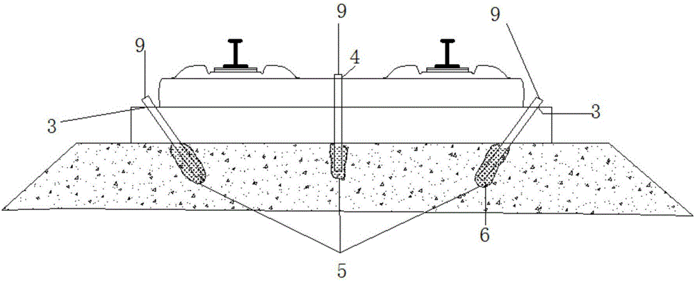
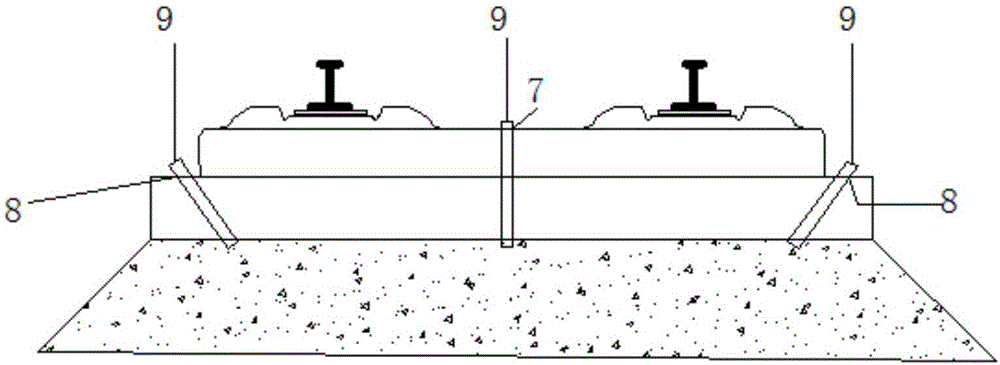
[0065] The following is attached Figure 3-5 , to illustrate the CRTS II ballastless track polymer bag grouting lifting and lateral jack correction method of the second embodiment of the present invention, the method includes the following:

[0066] (1) The layout position of grouting hole and filling hole, the lifting amount is determined

[0067] Before grouting, use high-precision level, total station, geological radar and other equipment to detect the rail surface and the empty area under the rail, compare with the design elevation, check the control limit of subgrade settlement and deformation in relevant specifications, and determine the uplift Correction position and lifting correction amount. Calculate the grouting hole diameter and layout spacing according to the actual situation on site. The diameter of grouting holes 3 and 4 and filling holes 7 and 8 should be 80mm, the spacing between filling holes should be 1.3m, and the spacing between grouting holes should be 3...


PUM

PropertyMeasurementUnit
Radiusaaaaaaaaaa

Abstract

The invention discloses a ballastless track grouting lifting and lifting correcting method. The method comprises the following steps: step 1: before lifting, using a high-precision level gauge to measure the track surface and under-track empty area, according to the measuring result, determining the lifting position and lifting quantity of a track board, and determining the arrangement position, space distance, hole diameter and hole depth of a grouting hole; step 2: calculating and determining the cutting position of a closing layer, and cutting the closing layer; step 3: arranging the grouting holes in the position to be lifted, preparing a polymer bag and arranging holes in the polymer bag; step 4: inserting a grouting pipe into the polymer bag, and fixing; step 5: installing the grouting pipe and the polymer bag in the grouting hole; step 6: executing the grouting lifting, monitoring in real time during the lifting process, and guaranteeing the track lifting elevation; and step 7: after executing certain amount of the grouting lifting, correcting the part to be corrected, monitoring the correcting process in real time, and guaranteeing the correcting displacement of the track. After completing the grouting, the high polymer bag and a grouting material carry out the compaction with the surrounding soil so as to form a self-formation pile. The solution is capable of realizing the rapid and accurate lifting of the upper structure of the track.

Description

technical field [0001] The patent of the invention belongs to the technical field of maintenance and repair of transportation infrastructure, and specifically relates to the technology of ballastless track structure polymer grouting lifting and mechanical device deviation correction. Background technique [0002] The ballastless track uses a reinforced concrete base plate instead of a ballast bed to distribute and transfer the wheel-rail force to the subgrade foundation. Compared with the ballasted track structure, the integral structural characteristics of the ballastless track make it have significant advantages in maintaining the stability and smoothness of the track, but it limits the adjustable range of the ballastless track structure, that is, only in the fastener The system allows the smoothness of the track structure to be repaired within an adjustable range. Similarly, in engineering practice, due to factors such as special engineering geology, construction quality...

Claims


Application Information

Patent Timeline
IPC IPC(8): E01B29/04
CPCE01B29/04
Inventor 冯青松董明
Owner BEIJING RUIWEI TIEKE HIGH SPEED RAIL ENG CO LTD
Why Eureka
Try Eureka