Composite-pile-cement-soil-pile partitioned composite foundation

A technology of cement-soil piles and composite foundations, which is applied in the direction of foundation structure engineering, roads, excavation, etc., can solve the problems of brittle fracture of the outer pile body, uneven settlement of uneconomical road surfaces, and reduced bearing capacity, so as to improve the vertical bearing capacity And the effect of vertical stiffness and control of uneven settlement

Inactive Publication Date: 2017-05-31
TIANJIN UNIV
View PDF3 Cites 2 Cited by
  • Summary
  • Abstract
  • Description
  • Claims
  • Application Information

AI Technical Summary

Problems solved by technology

[0005] Aiming at the defects existing in the prior art, the present invention provides a composite pile-cement-soil pile partition composite foundation, which solves the problem that the outer pile body of the traditional cement-soil composite foundation is prone to brittle fracture under a large bending moment, resulting in inner The brittle fractures of the piles occur sequentially, which leads to the instability of the embankment and the greatly reduced bearing capacity. At the same time, it solves the problem of high cost and uneconomical when reinforced concrete piles or composite piles are used for embankment treatment, and the method of equally spaced piles is adopted When the road surface is unevenly settled and the total settlement control effect is poor, the compressive and bending bearing capacity of the outer pile body cannot be fully utilized.

Method used


Image

  • Composite-pile-cement-soil-pile partitioned composite foundation
  • Composite-pile-cement-soil-pile partitioned composite foundation
  • Composite-pile-cement-soil-pile partitioned composite foundation

Examples


Embodiment Construction

[0017] The technical solution of the present invention will be further described in detail below in conjunction with the accompanying drawings and specific embodiments, and the described specific embodiments are only for explaining the present invention, and are not intended to limit the present invention.

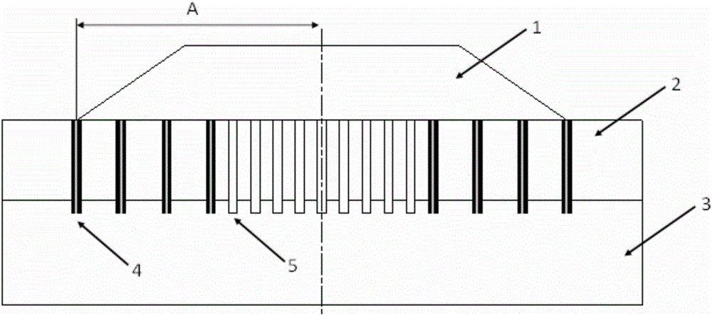
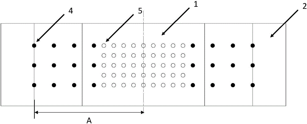
[0018] Such as figure 1 with figure 2 As shown, a composite pile-cement soil pile composite foundation proposed by the present invention includes outer piles and inner piles, and the area where the outer piles and inner piles are arranged is the area covered by embankment 1, wherein the The embankment 1 includes the embankment top surface and the embankment slopes on both sides of the embankment top surface. On the embankment cross section, the distance from the edge of the embankment slope to the centerline of the width of the embankment cross section is A, and the area where the outer piles are arranged is from The embankment side slopes on both sides extend to the cen...


PUM


Abstract

The invention discloses a composite-pile / cement-soil-pile partitioned composite foundation. The composite-pile / cement-soil-pile partitioned composite foundation comprises outer side piles and inner side piles. The region with the outer side piles and the inner side piles is the region where an embankment covers. The distance between the edges of the side slopes of the embankment and the center line of the width of the cross section of the embankment is A. The region is the region extending to the position of 1 / 5-3 / 4 A in the direction from the side slopes, on the two sides, of the embankment to the center line of the width of the cross section of the embankment. The residual region is the arrangement region of the inner side piles. The composite piles with the large pile intervals are adopted as the outer side piles, and the soil cement piles with the relatively-small pile intervals are adopted as the inner side piles. The composite-pile-cement-soil-pile partitioned composite foundation solves the problems that outer side pile bodies of a traditional cement soil pile composite foundation are likely to generate brittle rupture under the large bending moment, consequently inner side pile bodies sequentially generate brittle rupture, and the stability of the embankment is lost, and the bearing capacity is lowered greatly. The composite-pile / cement-soil-pile partitioned composite foundation has the beneficial effects that the construction is simple, the total sedimentation control effect is good, the compression resistance and bending capacity of the outer side pile bodies can be fully used, the safety is high, the applicability is high, and the economy is good.

Description

technical field [0001] The invention relates to a partition combined composite foundation which adopts composite piles and cement-soil piles mixedly, and belongs to the field of civil engineering foundations. Background technique [0002] In recent years, with the rapid development of my country's high-speed railway construction, higher requirements have been put forward for the construction speed of embankments and settlement control. In my country's coastal areas, the upper soil is mostly saturated soft clay, which has low shear resistance and poor drainage capacity, so the embankment is prone to instability and damage. In order to meet the requirements of rapid construction and settlement control, rigid piles and semi-rigid pile composite foundations have been more and more widely used. Cement-soil piles have the characteristics of high compressive bearing capacity, low cost, and fast construction speed, and are very suitable for engineering applications. Wide, but its v...

Claims


Application Information

Patent Timeline
Patent Type & Authority Applications(China)
IPC IPC(8): E02D17/20E01C3/00
CPCE02D17/207E01C3/00
Inventor 郑刚杨新煜周海祚孙佳羽
Owner TIANJIN UNIV
Why Eureka
Try Eureka