Automatic full-balance design method for high-speed gear shaping machine active movement inertia force

A design method and inertial force technology, applied in inertial force compensation, mechanical equipment, transmission devices, etc., can solve problems such as machine tool instability, part accuracy not meeting requirements, and low efficiency

Active Publication Date: 2017-05-31
宜昌长机科技有限责任公司
View PDF7 Cites 8 Cited by
  • Summary
  • Abstract
  • Description
  • Claims
  • Application Information

AI Technical Summary

Problems solved by technology

At present, in the actual high-speed operation of domestic gear shaping machines, the precision of parts cannot meet the requirements and the machine tools are extremely unstable. There is still a certain gap with foreign machine tools. As a result, the stroke speed of domest...

Method used


Image

  • Automatic full-balance design method for high-speed gear shaping machine active movement inertia force
  • Automatic full-balance design method for high-speed gear shaping machine active movement inertia force
  • Automatic full-balance design method for high-speed gear shaping machine active movement inertia force

Examples


Embodiment Construction

[0046] Embodiments of the present invention will be further described below in conjunction with the accompanying drawings.

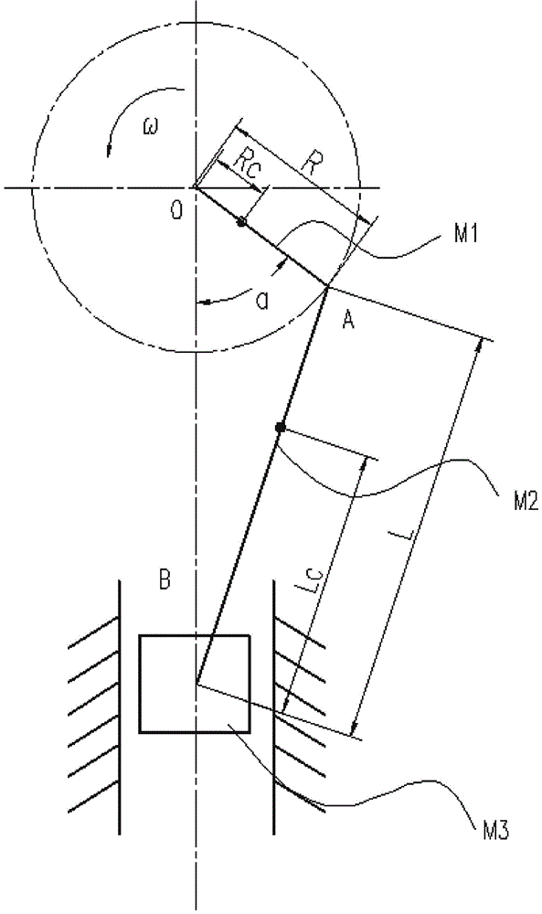
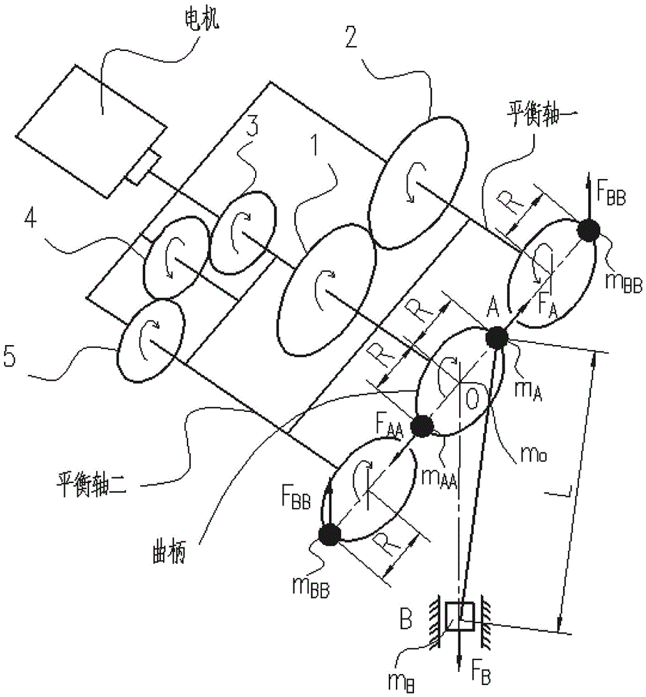
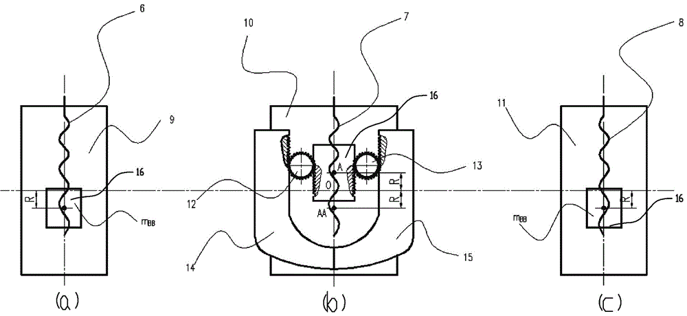
[0047] Such as Figure 1-3 , a high-speed gear shaping machine main motion inertial force automatic full balance design method, characterized in that it includes the following steps:

[0048] Step 1: Establish the displacement S, velocity V and acceleration α of the mechanism slider through the dynamic analysis of the centering upright slider crank mechanism 3 The mathematical models of are:

[0049]

[0050]

[0051] alpha 3 =Rω 2 (cosα+λcos2α) (3)

[0052] In the formula: λ=R / L; R is the length of the crank; ω is the constant rotational angular velocity of the crank; α is the rotation angle; L is the length of the connecting rod.

[0053] Step 2: According to the mass static substitution method that keeps the inertial force constant, the mass M of the crank is 1 With two lumped masses M centered at point O at the center of the crank and at ...


PUM


Abstract

The invention discloses an automatic full-balance design method for high-speed gear shaping machine active movement inertia force. The automatic full-balance design method for the high-speed gear shaping machine active movement inertia force is characterized in that the full-balance design method for gear shaping machine active movement, namely crank connecting link sliding block mechanism inertia force is disclosed, a computational formula for balance block mass added onto a crankshaft when inertia force is in full-balance is elicited, the purpose of full-balance inertia force is achieved when the length of the crankshaft is adjusted at will, and a very good dynamic balance effect is achieved in the actual industrial application of a high-speed gear shaping machine.

Description

technical field [0001] The present invention relates to a high-speed gear shaping machine main motion inertial force automatic full balance design method, in particular to a high-speed gear shaping machine crank connecting rod slider mechanism with different crank eccentric lengths to achieve a fully automatic inertial force balance method, which belongs to the gear shaping machine technology field. Background technique [0002] In recent years, with the rapid development of the power tool industry and the automobile industry, the demand for gear parts with small tooth widths has grown rapidly. These parts are especially suitable for mass production on gear shaping machines. In order to reduce costs and improve production efficiency, high-speed gear shaping Machines are used more and more widely. At present, in the actual high-speed operation of domestic gear shaping machines, the precision of parts cannot meet the requirements and the machine tools are extremely unstable. ...

Claims


Application Information

Patent Timeline
IPC IPC(8): F16F15/26F16H21/20
CPCF16F15/26F16F15/265F16H21/20
Inventor 罗成姜雨卢宇张全林
Owner 宜昌长机科技有限责任公司
Why Eureka
Try Eureka