
Illuminating light source for unmanned aerial vehicle to shoot

A lighting source and unmanned aerial vehicle technology, which is applied in the direction of light guides of lighting devices, light guides of lighting systems, and light sources, and can solve problems such as increasing costs

Inactive Publication Date: 2017-05-31
徐州奕创光电科技有限公司
View PDF5 Cites 5 Cited by
  • Summary
  • Abstract
  • Description
  • Claims
  • Application Information

AI Technical Summary

Problems solved by technology

If you make a direction control system for the lighting source alone, it will greatly increase the cost

Method used


Image

  • Illuminating light source for unmanned aerial vehicle to shoot
  • Illuminating light source for unmanned aerial vehicle to shoot
  • Illuminating light source for unmanned aerial vehicle to shoot

Examples


Embodiment 1

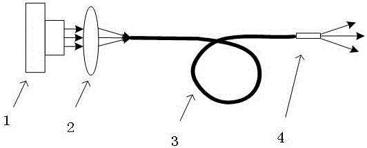
[0030] Such as figure 1 as shown,

[0031] An illumination light source for unmanned aerial vehicles, including a semiconductor laser, one side of the semiconductor laser is provided with a fiber coupling lens 2, one side of the fiber coupling lens 2 is provided with an optical fiber 3, and the laser light emitted by the semiconductor laser is collected by the fiber coupling lens 2 In the optical fiber 3, the self-focusing lens fixed on the camera of the drone platform is fixedly connected with the light-emitting end of the optical fiber 3, and illuminates the surface to be photographed after passing through the self-focusing lens.

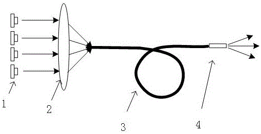
Embodiment 2

[0033] Such as figure 2 As shown, a lighting source for unmanned aerial vehicle shooting includes a combination of multiple semiconductor lasers in parallel. Received into the optical fiber 3 through the fiber coupling lens 2, the self-focusing lens fixed on the camera of the drone platform is fixedly connected with the light-emitting end of the optical fiber 3, and illuminates the surface to be photographed after passing through the self-focusing lens.

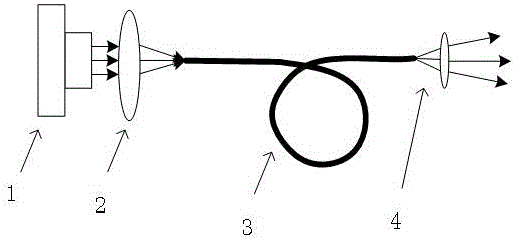
Embodiment 3

[0035] Such as image 3 Shown, a kind of illuminating light source that unmanned aerial vehicle photographs is used, comprises a semiconductor laser device, and the laser light that semiconductor laser device sends is received in optical fiber 3 through optical fiber coupling lens 2, is fixed on the spherical lens and optical fiber on the camera of unmanned aerial vehicle platform The light-emitting ends of 3 are fixedly connected together, and illuminate the surface to be photographed after passing through the spherical lens.

[0036] The present invention transmits the light from the light source 1 to the shooting camera of the drone platform through the optical fiber 3, so that the lighting source can be rotated with the rotation of the shooting camera, and finally the lighting surface and the shooting surface are always coincident, and will not follow When the UAV is flying in the air, it is separated by shaking; the lighting source is free from the limitation of the camer...


PUM


Abstract

The invention relates to an illuminating light source for an unmanned aerial vehicle to shoot. The illuminating light source comprises a light source. An optical fiber coupling lens is arranged on one side of the light source, an optical fiber is arranged on one side of the optical fiber coupling lens, and the optical fiber coupling lens is used for coupling light sent by the light source to the optical fiber; a light emitting end of the optical fiber is also connected to a light emitting lens which is fixed on a camera of a platform of the unmanned aerial vehicle for controlling the light emitting angle of the optical fiber to play a light receiving role. Compared with the prior art, according to the technical scheme, light of the light source is conducted to the camera on the platform of the unmanned aerial vehicle, so that the illuminating light source can rotate along with rotation of the camera, and finally, the illuminating surface and the shooting surface are overlaid all the way and will not be separated along jittering of the unmanned aerial vehicle during flight in air. The illuminating light source is free from limitation of the shooting camera and can be freely placed in an appropriate part of the unmanned aerial vehicle, so that design and heat dissipating design of the illuminating light source are further facilitated.

Description

technical field [0001] The invention relates to an illumination light source, in particular to an illumination light source for unmanned aerial vehicle shooting. Background technique [0002] At present, with the gradual maturity of drone technology, drone photography has gradually become a mainstream application of drones. Restricted by the light, the current drone photography is mostly limited to daytime. When shooting at night, although infrared cameras can be used for image acquisition, they cannot be widely used due to their low color resolution and fuzzy images. [0003] In order to realize the night photography function of the UAV, a lighting source is usually configured on the UAV. Ordinary lighting sources cannot be installed on the camera platform due to weight reasons, but can only be installed on the drone body. However, drones usually shake when flying, so that the light source will shake with the fuselage, making the lighting surface uncontrollable. If ther...

Claims


Application Information

Patent Timeline
IPC IPC(8): F21S8/10F21V8/00F21V5/04G03B15/02F21Y115/30
CPCG03B15/02F21S43/00F21V5/04F21V2200/13
Inventor 陈昱杨记冬
Owner 徐州奕创光电科技有限公司
Learn More