
High-temperature incineration refuse treatment device

A processing equipment and high temperature technology, applied in the field of high-temperature waste incineration processing equipment, can solve the problems of affecting the efficiency of waste treatment, insufficient combustion of waste, and large processing workload, so as to reduce the amount of exhaust dust, improve the combustion effect, and reduce the follow-up work. Effect

Active Publication Date: 2017-05-31
湖南未名环保科技有限公司
View PDF6 Cites 2 Cited by
  • Summary
  • Abstract
  • Description
  • Claims
  • Application Information

AI Technical Summary

Problems solved by technology

The existing garbage is generally incinerated during the treatment process to reduce the pollution of the environment by the garbage. The existing incineration equipment puts the garbage into incineration. During the incineration process, the garbage is not fully burned, and the incineration efficiency is low, which affects the efficiency of garbage treatment. A large amount of harmful gas is produced, and the post-processing workload is heavy

Method used


Image

  • High-temperature incineration refuse treatment device

Examples


Embodiment Construction

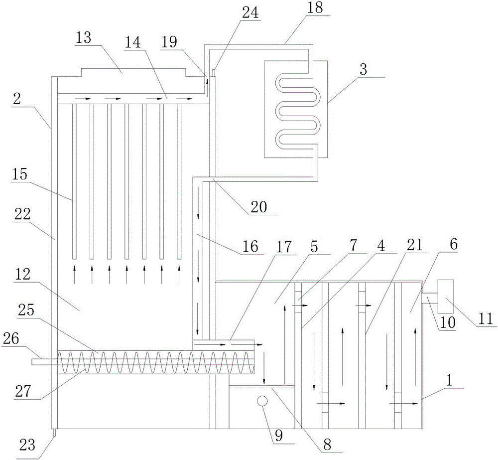
[0018] refer to figure 1 , the present invention proposes a high-temperature waste incineration treatment equipment, including a first furnace body 1, a second furnace body 2, a screw feeding mechanism, an internal circulation mechanism, and a water cooling box 3, wherein:

[0019] The first furnace body 1 has a chamber, the first vertical partition 4 is arranged in the chamber, the first vertical partition 4 separates the chamber into a combustion chamber 5 and an exhaust gas buffer chamber 6, and the top of the first vertical partition 4 is provided with a The combustion chamber 5 communicates with the exhaust gas buffer chamber 6 through a vent hole 7 , and the combustion chamber 5 is provided with a furnace bridge 8 and an oxygen supply device 9 . The first furnace body 1 is provided with an exhaust pipe 10 communicating with the exhaust gas buffer chamber 6, and the exhaust pipe 10 is provided with a fan 11; a plurality of second vertical partitions 21 are arranged at int...


PUM


Abstract

The invention provides a high-temperature incineration refuse treatment device. A combustion cavity and a tail gas buffering cavity are arranged in a first incinerator body. A second incinerator body is provided with a material storage cavity. A heating device is arranged at the bottom of the material storage cavity. A spiral feeding mechanism is used for conveying materials in the material storage cavity into the combustion cavity. An inner circulation mechanism comprises a first gas guide pipe, multiple second gas guide pipes, a third gas guide pipe, a fourth gas guide pipe and an outer gas guide pipe, wherein one end of the first gas guide pipe is sealed, the other end of the first gas guide pipe communicates with a gas outlet, the multiple second gas guide pipes are vertically arranged in the material storage cavity, the gas inlet end of each second gas guide pipe extends into the middle of the material storage cavity, the gas outlet end of each second gas guide pipe communicates with the first gas guide pipe, the gas inlet end of the third gas guide pipe communicates with a gas inlet, the gas outlet end of the third gas guide pipe communicates with the gas inlet end of the fourth gas guide pipe, the gas outlet end of the fourth gas guide pipe extends into the combustion cavity, one end of the outer gas guide pipe communicates with the gas outlet, and the other end of the gas guide pipe penetrates through a cooling water tank to communicate with the gas inlet. The high-temperature incineration refuse treatment device is high in refuse treatment efficiency and in refuse combustion capacity and achieves complete combustion of refuse.

Description

technical field [0001] The invention relates to the technical field of waste incineration treatment, in particular to high-temperature waste incineration treatment equipment. Background technique [0002] In densely populated cities, garbage disposal is a headache. Common way is to send to landfill after collecting for landfill treatment, or burn with incinerator. But both create environmental concerns, and ending overconsumption could further reduce landfill saturation. Waste disposal in landfills not only pollutes the groundwater and emits a bad smell, but many cities have less and less landfill area. Incineration inevitably produces toxic gases that harm living organisms. Most cities are researching ways to reduce waste and encourage recycling. The existing garbage is generally incinerated during the treatment process to reduce the pollution of the environment by the garbage. The existing incineration equipment puts the garbage into incineration. During the incinerati...

Claims


Application Information

Patent Timeline
Patent Type & Authority Applications(China)
IPC IPC(8): F23G5/04F23G5/16F23G5/44
CPCF23G5/04F23G5/16F23G5/444F23G2205/121
Inventor 曹文波张文锐魏凌敏舒志强唐武才李启仁李文龙郎志中
Owner 湖南未名环保科技有限公司
Learn More