Flue gas treatment system biogas utilization method and system

A flue gas treatment system and flue gas treatment technology, applied in the direction of combustion methods, combustion types, incinerators, etc., can solve the problems of waste of resources, waste of biogas with high calorific value, etc., and achieve the effect of saving electricity and improving overall efficiency

Active Publication Date: 2017-05-31
北京高安屯垃圾焚烧有限公司
View PDF6 Cites 2 Cited by
  • Summary
  • Abstract
  • Description
  • Claims
  • Application Information

AI Technical Summary

Problems solved by technology

[0003] Disadvantages of biogas torch: directly burning biogas, wasti

Method used


Image

  • Flue gas treatment system biogas utilization method and system

Examples


Embodiment 1

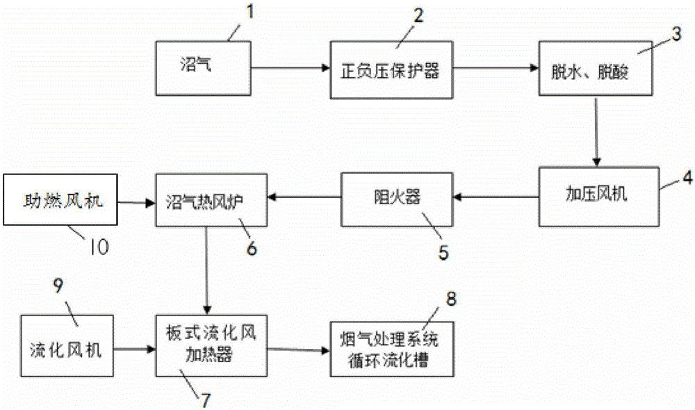
[0017] Embodiment 1: as figure 1 as shown,

[0018] A biogas utilization system, the biogas device 1 is connected to the positive and negative pressure protector 2, the positive and negative pressure protector 2 is connected to the dehydration and desulfurization device 3, the dehydration and desulfurization device 3 is connected to the biogas pressurization fan 4, and the biogas pressurization fan 4 is connected to the flame arrester 5 , the flame arrester 5 is connected to the biogas hot blast stove 6, and the combustion-supporting fan 10 sends air into the biogas hot blast stove 6. After ignition, the biogas stove automatically burns to generate high-temperature flue gas, which is sent to the plate-type fluidized air heater 7, and the fluidized fan 9 will flow After pressurized, the fluidizing air is sent to the plate-type fluidizing air heater 7, and the heated fluidizing air is sent to the bottom 8 of the circulating fluidizing tank of the flue gas treatment system.

[0...


PUM


Abstract

The invention relates to a flue gas treatment system biogas utilization method, and belongs to the field of flue gas treatment technology. Biogas is connected with a dehydration and desulfurization device through a positive and negative pressure protection device, the dehydration and desulfurization device is connected with a pressure fan, the pressure fan is connected a flame arrester, the flame arrester is connected to a biogas furnace, a combustion fan feeds air into the biogas furnace, the biogas furnace is connected to a fluidized air plate heater, fluidized air is heated via the plate heater with the aid of biogas burning heat, and the electric heating step of fluidized air is replaced. The method has the advantages that the original fluidized air electric heater is replaced with the biogas hot blast furnace. The high-temperature flue gas after the combustion of biogas heats circulating fluidized air through the fluidized air plate heater to realize waste recycling and save electricity, and environmental pollution caused by biogas is reduced.

Description

technical field [0001] The invention relates to a biogas utilization method and system, belonging to the technical field of flue gas treatment. Background technique [0002] For waste incineration power generation enterprises, a large amount of leachate will be produced during the fermentation process of waste stacking, and a large amount of biogas will be produced during the process of leachate treatment. The biogas is directly discharged into the atmosphere after being burned by a flare. [0003] Disadvantages of biogas torch: directly burning biogas, wasting biogas with high calorific value, resulting in waste of resources. Contents of the invention [0004] In order to realize the comprehensive utilization of resources and achieve the purpose of energy saving and environmental protection, the present invention provides a method and system for utilizing biogas in a flue gas treatment system. [0005] A method for utilizing biogas in a flue gas treatment system, compri...

Claims


Application Information

Patent Timeline
IPC IPC(8): F23G7/06
CPCF23G7/06F23G2209/14
Inventor 雷艳青
Owner 北京高安屯垃圾焚烧有限公司
Why Eureka
Try Eureka