
Method for measuring optical fiber dispersion based on optical switch laser beat-frequency system

A technology for optical fiber dispersion and system measurement, which is used in testing optical fiber/optical waveguide equipment, reflectometers for detecting backscattered light in the frequency domain, and testing optical performance. Advanced problems, to achieve the effect of simplified measurement process, simple structure and low cost

Inactive Publication Date: 2017-05-31
HENAN NORMAL UNIV
View PDF16 Cites 5 Cited by
  • Summary
  • Abstract
  • Description
  • Claims
  • Application Information

AI Technical Summary

Problems solved by technology

There are many methods for measuring optical fiber dispersion, mainly three kinds, instant delay method, interference method and phase shift method, among which the measurement accuracy of time delay method is mainly limited by the width of optical pulse, the bandwidth of photodetector and the stability of laser light source and electronic devices The phase-shift method is widely used, and commercial dispersion measurement instruments basically use the phase-shift method, but the phase-shift method usually requires a very stable tunable laser, and even needs to be combined with a vector network analyzer to achieve frequency sweep, resulting in measurement costs Greatly increased; interferometric measurement is a method that people have studied most in recent years. It has high measurement accuracy, relatively simple structure, and can measure short optical fibers. It is suitable for dispersion measurement of expensive special optical fibers, such as photonic crystal optical fibers.
The above methods generally have the defects of complex structure, inconvenient operation and high measurement cost. Therefore, it is necessary to design a method for measuring optical fiber dispersion based on an optical switch laser beat frequency system.

Method used


Image

  • Method for measuring optical fiber dispersion based on optical switch laser beat-frequency system
  • Method for measuring optical fiber dispersion based on optical switch laser beat-frequency system
  • Method for measuring optical fiber dispersion based on optical switch laser beat-frequency system

Examples


Embodiment Construction

[0015] The above-mentioned contents of the present invention are described in further detail below through the embodiments, but this should not be interpreted as the scope of the above-mentioned themes of the present invention being limited to the following embodiments, and all technologies realized based on the above-mentioned contents of the present invention all belong to the scope of the present invention.

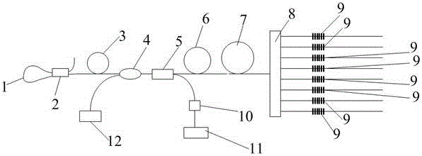
[0016] Such as figure 1 As shown, the method for measuring fiber dispersion based on the optical switch laser beat frequency system, the measurement system mainly consists of a fiber loop mirror 1, a first coupler 2, a saturable absorber 3, a wavelength division multiplexer 4, a second coupler 5, 980 Pumping light source 12, erbium-doped optical fiber 6, photodetector 10, spectrum analyzer 11, optical fiber to be tested 7, optical switch 8 and multiple groups of fiber gratings 9, wherein multiple groups of fiber gratings 9 and fiber loop mirrors constitute a laser reson...


PUM


Abstract

The invention discloses a method for measuring optical fiber dispersion based on an optical switch laser beat-frequency system, which is characterized in that optical fiber gratings with different central wavelengths are selected through adjusting an optical switch, variations in beat frequency in a laser resonant cavity are realized, variations in laser beat frequency before and after an optical fiber to be measured is added to an optical path are measured respectively by using a spectrum analyzer, and a relation between the variation in laser beat frequency before and after the optical fiber to be measured is added to the optical path and the corresponding dispersion of the optical fiber to be measured is established, so that measurement for the dispersion of the optical fiber to be measured under different wavelengths is enabled to be converted into measurement for the variation in laser beat frequency, and measurement for the dispersion of the optical fiber to be measured is realized through data processing. According to the invention, the optical fiber dispersion is measured by using multi-longitudinal mode beat-frequency signals, so that the method is not affected by the system loss and light source fluctuations, and measurement for the dispersion of the optical fiber to be measured is successfully realized. The method is not only good in stability, simple in structure of a measurement system and low in cost, but also converts optical signal measurement into electric signal measurement, thereby being convenient to perform data processing.

Description

technical field [0001] The invention belongs to the technical field of optical fiber dispersion measurement, and in particular relates to a method for measuring optical fiber dispersion based on an optical switch laser beat frequency system. Background technique [0002] The dispersion problem of the optical fiber communication system has always been a hot spot that people pay attention to. With the continuous improvement of the system transmission rate, the intersymbol interference caused by various types of dispersion has become one of the main limiting factors of the capacity of the optical communication system. Technical means to compensate for dispersion. But for the DWDM system, a certain amount of dispersion is needed to reduce the four-wave mixing caused by nonlinear effects. Therefore, before the system is put into use, various dispersions should be measured to determine the required dispersion management scheme. [0003] The essence of optical fiber dispersion me...

Claims


Application Information

Patent Timeline
Patent Type & Authority Applications(China)
IPC IPC(8): G01M11/02
CPCG01M11/3172
Inventor 王旭李小康陈龙飞张玲娟
Owner HENAN NORMAL UNIV
Learn More