
Multi-focal Raman spectrumacquisition instrument based on diffractive optical element

A diffractive optical element and Raman spectroscopy technology, applied in the field of multi-focal Raman spectrum acquisition instruments, can solve the problems of slow Raman spectrum acquisition efficiency, weak Raman signal, long integration time, etc., to expand the number and application. field, the effect of improving collection efficiency

Inactive Publication Date: 2017-05-31
TIANJIN UNIV
View PDF7 Cites 5 Cited by
  • Summary
  • Abstract
  • Description
  • Claims
  • Application Information

AI Technical Summary

Problems solved by technology

[0005] Second, the Raman signal is weak, so a long integration time is required for acquisition, which leads to a slow acquisition efficiency of the Raman spectrum, and a large amount of time is consumed when scanning a sample

Method used


Image

  • Multi-focal Raman spectrumacquisition instrument based on diffractive optical element
  • Multi-focal Raman spectrumacquisition instrument based on diffractive optical element
  • Multi-focal Raman spectrumacquisition instrument based on diffractive optical element

Examples


Embodiment 1

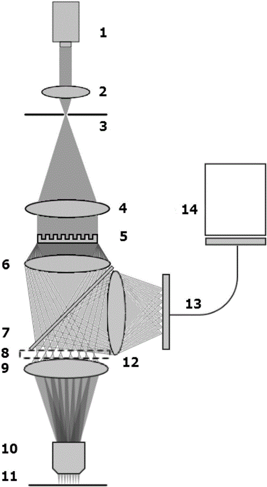
[0026] A multi-focus Raman spectrum acquisition instrument based on diffractive optical elements, see figure 1 , the multi-focus Raman spectrum acquisition instrument mainly has two functions: low incident light power Raman spectrum detection, and high-speed micro-Raman measurement.

[0027] Among them, the schematic diagram of the optical path of the instrument is as follows: figure 1 As shown, compared with the ordinary Raman spectrum acquisition instrument, one converging spot can be dispersed into multiple focused spots, and different signal processing methods can be adopted in the later stage according to the purpose of collecting signals.

[0028] according to figure 1 The acquisition instrument is set up as shown, and input lasers of different intensities are selected according to the sample 11 to be tested and the sampling requirements, and the diffractive optical element 5 and the optical fiber 13 with matching parameters are selected to collect Raman signals, that i...

Embodiment 2

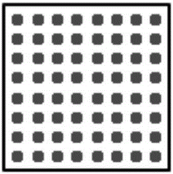
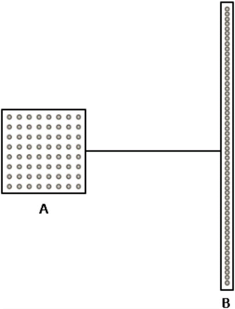
[0034] Combine below figure 1 , figure 2 and image 3 The scheme in Example 1 is further introduced, see the following description for details:

[0035] Compared with the ordinary Raman spectrum acquisition instrument, it has the advantages of reducing the damage of the focused high-intensity spot to the sample 11 and improving the collection efficiency of the Raman spectrum. The specific implementation methods are as follows:

[0036] The schematic diagram of the optical path of the instrument of the embodiment of the present invention is as follows figure 1 shown. Firstly, a laser 1 with a suitable frequency is selected, and the emitted laser light passes through the first converging lens 2 , the pinhole 3 , and the second converging lens 4 to become a wider parallel laser beam and irradiates the diffractive optical element 5 . The incident laser beam is split and converged by the diffractive optical element 5 and the third converging lens 6, and then adjusted by the fo...


PUM


Abstract

The invention discloses a multi-focal Raman spectrum acquisition instrument based on adiffractive optical element, and effectively solves the technical problem that higher incident intensity affects Raman signal acquisition, so that the acquisition efficiency of Raman spectrum can be further improved, and micro Raman measurement is realized. The diffractive optical element is introduced into a Raman spectrometer, so that light spot energy focused on a sample to be tested can be dispersed, the damage of focused high-strength light spots to the sample to be tested is reduced, and an application field of the Raman spectrum can be expanded; meanwhile, the number of focal spots can be effectively increased, so that the collecting efficiency of the Raman spectrum is improved, and high-speed micro Raman is realized. The multi-focal Raman spectrum acquisition instrument provided by the invention has a wide prospect on researching a laser intensity sensitivity system.

Description

technical field [0001] The invention relates to the technical field of Raman spectrum acquisition, in particular to a multi-focus Raman spectrum acquisition instrument based on diffractive optical elements. Background technique [0002] The Raman scattering effect was first discovered by Indian scientist C.V. Raman in 1928. With the emergence and improvement of lasers and the improvement of weak light detection technology, Raman spectroscopy detection technology based on Raman scattering effect has been developed. Since then, Raman spectroscopy has been widely used in research fields such as physics, chemistry, biology, and medicine. [0003] However, the currently commonly used Raman spectrum acquisition instruments have the following two disadvantages: [0004] First, the Raman signal requires a strong laser as the excitation, but the obtained Raman signal is very weak, and the high-power laser will damage the light-absorbing material. For example, the measurement of the...

Claims


Application Information

Patent Timeline
Patent Type & Authority Applications(China)
IPC IPC(8): G01N21/65G01N21/01
CPCG01N21/65G01N21/01
Inventor 马翔云王慧捷王洋陈达李奇峰
Owner TIANJIN UNIV
Learn More