Current sampling circuit

A current sampling and circuit technology, applied in the direction of measuring current/voltage, only measuring current, measuring electrical variables, etc., can solve the problems of reducing current detection speed, small gain-bandwidth product GBW, and impact, so as to reduce impact and suppress glitches Effect

Inactive Publication Date: 2017-05-31
UNIV OF ELECTRONICS SCI & TECH OF CHINA
View PDF3 Cites 10 Cited by
  • Summary
  • Abstract
  • Description
  • Claims
  • Application Information

AI Technical Summary

Problems solved by technology

[0004] However, this inductor current sampling circuit requires the error amplifier EA to have a high gain for sampling accuracy, and based on stability considerations, a compensation network is required, so that the gain-bandwidth product GBW of the error amplifier EA is relatively small, which reduces the current detection speed; Moreover, when the switching frequency of the switching power supply continues to increase, the glitch caused by the switching signal at the input of the error amplifier EA will have a serious impact on the obtained sampling current

Method used


Image

  • Current sampling circuit
  • Current sampling circuit
  • Current sampling circuit

Examples


Embodiment Construction

[0029] Below in conjunction with accompanying drawing and embodiment, describe technical solution of the present invention in detail:

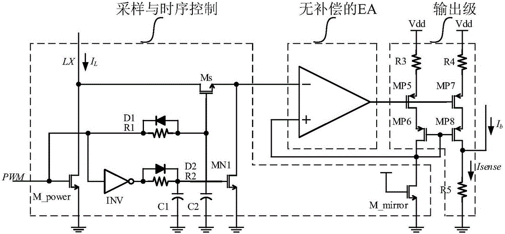
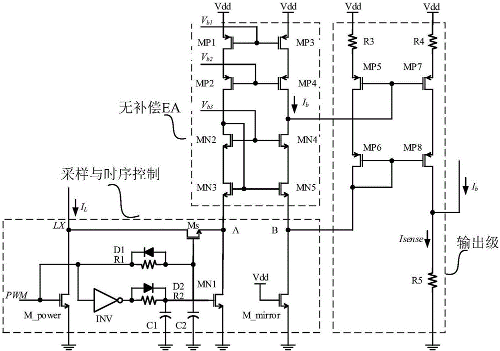
[0030] Such as image 3 As shown, it is a specific circuit diagram of the present invention, including a sampling and timing control module, an uncompensated error amplifier EA module and an output stage, wherein the input terminal of the sampling and timing control module is connected to the inductor current I L , its two output terminals are respectively connected to the non-inverting input terminal and the inverting input terminal of the error amplifier EA module without compensation; the input terminal of the output stage is connected to the output terminal of the error amplifier EA module without compensation, and its output The terminal outputs the sampling current Isense.

[0031] The sampling and timing control module includes a power tube M_power, a sampling mirror tube M_mirror, a protection tube Ms, a first diode D1, a second diode...


PUM


Abstract

The invention belongs to the technical field of integrated circuits and particularly relates to a current sampling circuit. The current sampling circuit comprises a sampling and time sequence control module, an uncompensated error amplifier EA module and an output stage, wherein the input end of the sampling and time sequence control module is connected with inductive current IL, two output ends of the sampling and time sequence control module are connected with the in-phase input end and the inverted input end of the uncompensated error amplifier EA module respectively, the input end of the output stage is connected with the output end of the uncompensated error amplifier EA module, and the output end of the output stage outputs sampling current Isense. The current sampling circuit has the advantages that the uncompensated error amplifier EA module guarantees sufficient gain and requires no compensating circuit, so that a GBW (gain bandwidth product) of an error amplifier EA is increased to 10 M and above; a time sequence control network of the sampling and time sequence control module restrains burr generated by switching signals, so that influences of PMW signals and LX dot signals on the input end of the uncompensated error amplifier EA and final sampling output current are lowered.

Description

technical field [0001] The invention belongs to the technical field of integrated circuits, and in particular relates to a current sampling circuit. Background technique [0002] Due to its high efficiency and high stability, the switching power supply has an irreplaceable role in the application field of electronic technology. The effective detection of the inductor current can not only realize the circuit loop control, but also play the role of overcurrent protection for the circuit. , so accurate and fast current detection is very critical. [0003] The traditional current sampling circuit structure such as figure 1 As shown, through a mirror tube M_mirror proportional to the size of the power tube M_power, the high-gain uncompensated error amplifier EA is used to clamp the drains of the power tube M_power and the mirror tube M_mirror, so that the current passing through the mirror tube M_mirror is proportional shrinking inductor current. [0004] However, this inducto...

Claims


Application Information

Patent Timeline
Patent Type & Authority Applications(China)
IPC IPC(8): G01R19/00
CPCG01R19/0092
Inventor 罗萍王康乐邱双杰刘泽浪黄龙黄锴甄少伟贺雅娟张波
Owner UNIV OF ELECTRONICS SCI & TECH OF CHINA
Why Eureka
Try Eureka