Low-sidelobe robust adaptive beamforming method

An adaptive beam and low side lobe technology, applied in radio wave measurement systems, instruments, etc., can solve the problems of beamformer output signal-to-interference-noise ratio decrease, wave arrival direction error, etc., to achieve anti-interference reduction and anti-mobile interference Effect

Inactive Publication Date: 2017-05-31
NORTHWESTERN POLYTECHNICAL UNIV
View PDF7 Cites 13 Cited by
  • Summary
  • Abstract
  • Description
  • Claims
  • Application Information

AI Technical Summary

Problems solved by technology

[0007] In order to solve the problem that the signal-to-interference-noise ratio of the beamformer output is seriously reduced due to practical problems such as mutual coupling and direction-of-arrival errors in the existing methods, the present invention proposes a robust adaptive beamforming algorithm

Method used


Image

  • Low-sidelobe robust adaptive beamforming method
  • Low-sidelobe robust adaptive beamforming method
  • Low-sidelobe robust adaptive beamforming method

Examples


Embodiment Construction

[0050] Now in conjunction with embodiment, accompanying drawing, the present invention will be further described:

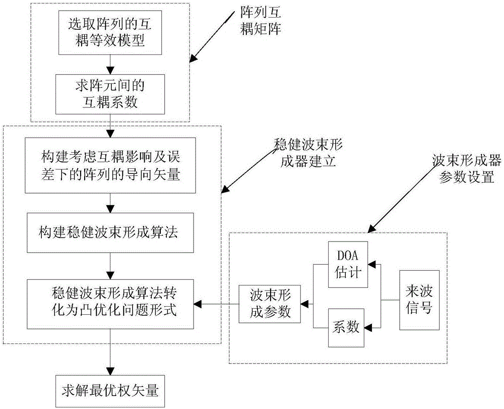
[0051] figure 1 is the overall flowchart of the robust low sidelobe beamformer of the present invention, such as figure 1 shown, including the following steps:

[0052]Step S100, first, according to the array form, find the mutual coupling coefficient between array elements and establish a mutual coupling equivalent model;

[0053] Step S200, constructing a robust beamforming algorithm with low sidelobes

[0054] Step S300, selecting the parameters of the beamformer

[0055] Step S400, obtain the optimal weight vector corresponding to the array.

[0056] The invention realizes the two purposes of low sidelobe and null trapping to interference while ensuring the robustness of the adaptive beamformer. When the side lobe level coefficient is selected too large, the effect of the array on zero will be reduced, and if the side lobe level coefficient is selected t...


PUM


Abstract

The invention relates to a low-sidelobe robust adaptive beamforming method. Firstly, an optimal criterion based on poorest performance is established, and it is ensured by adopting the beamforming method that lower null level can be obtained while low sidelobes are formed when array errors exist after cross coupling correction; then, a new beamforming system is established by combining a robust low-sidelobe theory and can adapt to interference competition and reduction of sidelobe level and achieve wide null. Especially, the system can select reasonable parameters in a self-adaptive mode according to an input signal, so that a beam forming device can obtain unified low sidelobe levels under different receiving signals.

Description

technical field [0001] The invention relates to the technical field of array signal processing, in particular to a low sidelobe robust adaptive zero-to-zero beamforming method. Background technique [0002] Adaptive beamforming uses an adaptive algorithm to process the desired signal and interference signal received by the array and form a corresponding beam, so as to enhance the useful signal or the signal that needs direction while suppressing the interference, and realize the harsh enemy interference and electromagnetic compatibility. The purpose of improving the anti-interference ability of radar, communication and other systems in the environment. However, in practical applications, due to errors such as mutual coupling, observation direction error, and array manifold error, the real expected signal of the array does not match the ideal expected signal direction. Conventional beamformers, such as the Capon beamformer, are built on the condition that the expected signal...

Claims


Application Information

Patent Timeline
Patent Type & Authority Applications(China)
IPC IPC(8): G01S7/02
CPCG01S7/02
Inventor 赵中惠赵惠玲
Owner NORTHWESTERN POLYTECHNICAL UNIV
Why Eureka
Try Eureka