Depth image enhancement method of tof camera

A TOF camera, depth image technology, applied in image enhancement, graphic image conversion, image data processing, etc., can solve the problem that the resolution of depth image is not as good as that of ordinary color image, the limitation of TOF camera market promotion and application, and the noise interference of depth value of depth image. and other problems, to achieve the effect of ensuring the quality of interpolation, improving the quality of depth images, and improving the effect of interpolation.

Active Publication Date: 2019-05-24
CHANGCHUN UNIV OF SCI & TECH
View PDF7 Cites 0 Cited by
  • Summary
  • Abstract
  • Description
  • Claims
  • Application Information

AI Technical Summary

Problems solved by technology

[0005] However, the depth image obtained by the TOF camera has the following defects: the resolution of the depth image is far lower than that of the ordinary color image; the depth value of the depth image is disturbed by significant noise; the depth value of the depth image at the edge of the object is prone to appear error
These defects have brought some limitations to the marketing and application of TOF cameras
Therefore, it is of great significance to study the enhancement technology of depth image and improve the quality of TOF depth image in view of the low resolution of depth image of TOF camera and the significant interference of depth value by noise.

Method used


Image

  • Depth image enhancement method of tof camera
  • Depth image enhancement method of tof camera
  • Depth image enhancement method of tof camera

Examples


Embodiment 1

[0085] Embodiment 1: Set the interpolation magnification of the depth image to N=8

[0086] (1) Using the image averaging method to suppress the noise of the collected depth images, the averaged results of 10 depth images are as follows Figure 5 shown;

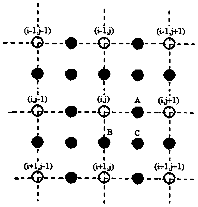
[0087] (2) Perform the following steps for each pixel in the low-resolution depth image to complete the 2-fold interpolation enlargement of the depth image.

[0088] 1. Determine whether the pixel point (i, j) belongs to the edge area.

[0089] According to formula (1), using W 1 , W 2 , W 3 , W 4 The four direction templates are operated separately. In this example, the edge detection threshold T is set to 50, when max(|R 1 |,|R 2 |,|R 3 |,|R 4 |)>50, the pixel belongs to the edge area, and the direction corresponding to the maximum value is the edge direction; otherwise, the pixel belongs to the smooth area.

[0090] 2. If the pixel point (i, j) belongs to the smooth area, use formulas (2), (3), and (4) to calcul...

Embodiment 2

[0099] Embodiment 2: Set the interpolation magnification of the depth image to N=10

[0100] (1), use the image averaging method to carry out noise suppression on the collected depth images, in this example, 10 depth images are used for averaging;

[0101] (2), each pixel in the low-resolution depth image is operated according to the following steps, and the 2-fold interpolation amplification of the depth image is completed;

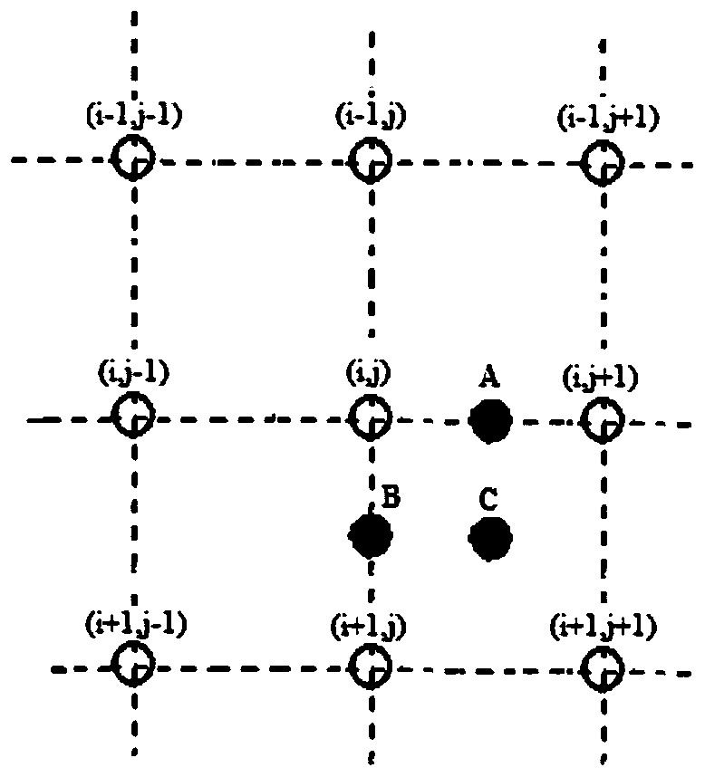
[0102] 1. Determine whether the pixel point (i, j) belongs to the edge area;

[0103] According to formula (1), using image 3 The four direction templates are operated separately. In this example, the edge detection threshold T is set to 50, when max(|R 1 |,|R 2 |,|R 3 |,|R 4 |)>50, the pixel belongs to the edge area, and the direction corresponding to the maximum value is the edge direction; otherwise, the pixel belongs to the smooth area;

[0104] 2. If the pixel point (i, j) belongs to the smooth area, use the formulas (2), (3), and (4) to cal...


PUM


Abstract

The invention relates to a depth image enhancement method for a TOF camera, and belongs to a depth image processing method. The method comprises the steps of firstly performing noise suppression processing on a depth image; and secondly performing interpolation amplification on the low-resolution TOF depth image by utilizing an inter-pixel distance and edge direction information in the image. According to the method, the resolution of the depth image is increased, and the visual quality of the depth image is improved; the method can be applied to the occasion for enhancing the depth image collected by the TOF camera and the like; and a depth image interpolation algorithm also can be popularized and applied to the occasion for interpolation amplification of other images.

Description

technical field [0001] The invention relates to a method for enhancing a depth image collected by a TOF camera, in particular to a method for interpolating and enlarging a TOF depth image by using the distance between pixels and edge direction information in the image. Background technique [0002] Each pixel in the depth image represents the distance from a certain point in the scene to the camera imaging plane, which describes the geometric information of the three-dimensional scene, and has always been the focus and hotspot of research in the field of computer vision. [0003] The 3D ranging camera based on the time-of-flight (TOF) principle can calculate the distance information of the object surface by measuring the time difference between the active light emitted to the object surface and reflected back, and can collect the 3D geometric information of the object surface in real time. A breakthrough in information acquisition methods is bound to promote the development ...

Claims


Application Information

Patent Timeline
Patent Type & Authority Patents(China)
IPC IPC(8): G06T5/00G06T3/40
CPCG06T3/4007G06T3/4023G06T3/403G06T5/002
Inventor 王宇朴燕孙荣春
Owner CHANGCHUN UNIV OF SCI & TECH
Why Eureka
Try Eureka