
Software and hardware cooperating design method for arithmetic acceleration

A technology of software-hardware collaboration and design methods, applied in computing, special data processing applications, instruments, etc., can solve problems such as insufficient optimization of the system, inability to achieve hardware scale and performance, loss of high-level comprehensive fineness, etc.

Inactive Publication Date: 2009-07-29
BEIHANG UNIV
View PDF0 Cites 14 Cited by
  • Summary
  • Abstract
  • Description
  • Claims
  • Application Information

AI Technical Summary

Problems solved by technology

[0009] Defects of the software-hardware collaborative design method based on intellectual property modules (IP): 1) Lost the fineness of high-level synthesis, and cannot adjust and optimize the specific functions of the selected intellectual property module (IP) according to the characteristics of the data flow graph; 2) Although in order to meet the needs of large-scale task flow graphs, the scale of functional units has been increased from simple operators to intellectual property modules (IP), but this mechanical increase still cannot achieve the true orientation of specific system constraints. Flexibly grasp the scale and performance of the hardware; 3) It is necessary to carefully adjust the interface timing between intellectual property modules (IP), which increases the design burden and makes the system not optimized enough
In the sense of software-hardware collaborative design, it means that the software-hardware collaborative design method based on intellectual property modules (IP) is a "semi-custom" design method, and it cannot flexibly adjust the proportional relationship between software and hardware according to system constraints.

Method used


Image

  • Software and hardware cooperating design method for arithmetic acceleration
  • Software and hardware cooperating design method for arithmetic acceleration
  • Software and hardware cooperating design method for arithmetic acceleration

Examples


Embodiment Construction

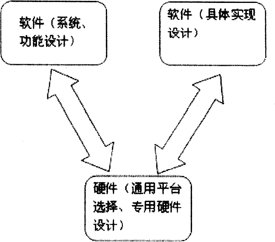
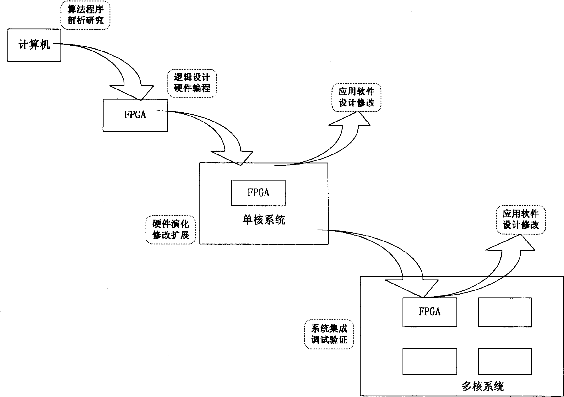
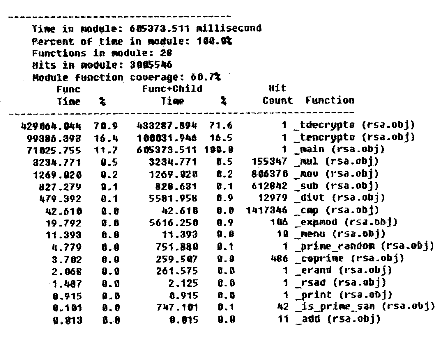
[0047] See figure 1 , figure 2 , image 3 , Figure 4 , Figure 5 , Image 6 As shown, an algorithm-accelerated software-hardware collaborative design method of the present invention, the specific implementation steps of the method are as follows:

[0048] Step 1: Algorithm and software static analysis. The mathematical principle of the algorithm can be verified by software such as Matlab, and then converted into an executable language such as C language to be realized on a PC or a special target hardware platform (such as an embedded device).

[0049] Step 2: Use software analysis tools to conduct dynamic measurement and analysis of software operation, and obtain basic data diagrams of software operation. The software tool that this step needs has the quantify in the IBM Rational suite that generates function call graph; Generate function running time and access times (as image 3 ) analysis (profile) software, such as VC profile under the Windows environment Visual C...


PUM


Abstract

The invention discloses a software and hardware collaborative design method of algorithm acceleration. The method has six steps of: step 1: static analysis of algorithm and software; step 2: using software analysis tools to carry out dynamic actual measurement analysis of the software so as to obtain a basic data chart of software operation; step 3: making overall structure and function design of a multi-core hardware system by combination of system requirements, the algorithm analysis and the software actual measurement analysis data; step 4: using appropriate modeling tools (RML) to describe the whole system; step 5: constructing a function process abstract chart GCG (including a function call chart of operation time parameters) on the base of the step 2 and discussing the distribution of the software in the multi-core system by using the chart GCG as the subject; and step 6: carrying out the software and hardware realization of a prototype system according to a proposal obtained from the step 5 and evaluating the realization results. The method has good compatibility, is applicable to the urgent demand for the design of a multi-core system on chip (SOC) and promotes the improvement of multi-core design tools. The method has very high utility value and promising application prospect.

Description

(1) Technical field [0001] The invention relates to a design method, in particular to an algorithm-accelerated software-hardware collaborative design method. It is a network security RSA algorithm based on hardware prototype evolution, and belongs to the technical fields of integrated circuit, system on chip (SOC), and embedded system design. (2) Background technology [0002] Software-hardware co-design is not only a design technique, but also a new design methodology. Its core problem is to coordinate software subsystems and hardware subsystems. [0003] The definition of software-hardware co-design has not yet been completely consistent, mainly in the following categories: [0004] David W. Franke (David W. Franke) and Martin K. Purvis (Martin K. Purvis) believe: "Software and hardware co-design is a kind of combination of software and hardware in the initial stage of the design process. A design method that is considered in combination to obtain design flexibility and ...

Claims


Application Information

Patent Timeline
IPC IPC(8): G06F17/50
Inventor 王翔左可
Owner BEIHANG UNIV
Learn More