High efficiency silicon chip cleaning equipment for silicon solar production
A technology for cleaning equipment and solar energy, which is used in the manufacture of final products, photovoltaic power generation, electrical components, etc., can solve the problems of poor cleaning effect, slow cleaning speed, and large workload, and achieve good cleaning effect, fast cleaning speed, and work efficiency. small amount of effect
- Summary
- Abstract
- Description
- Claims
- Application Information
AI Technical Summary
Problems solved by technology
Method used
Image

Examples
Embodiment 1
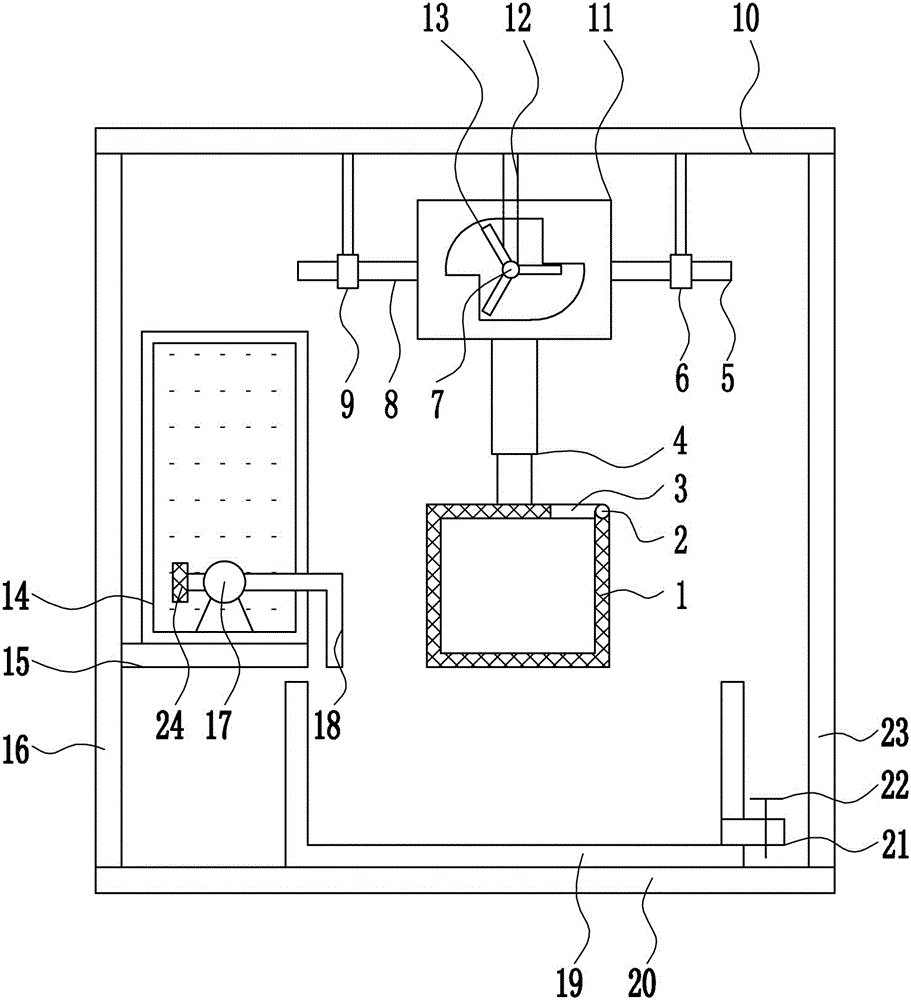
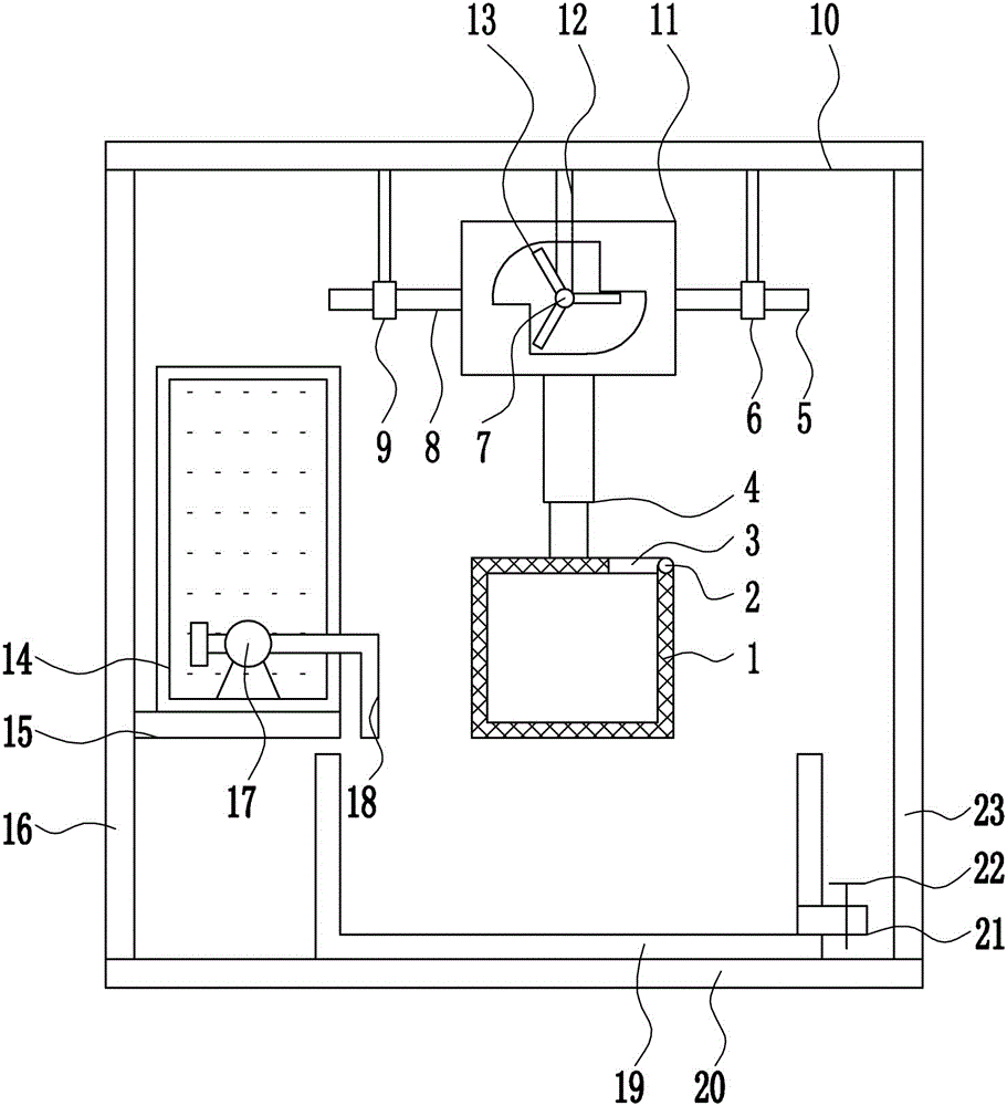
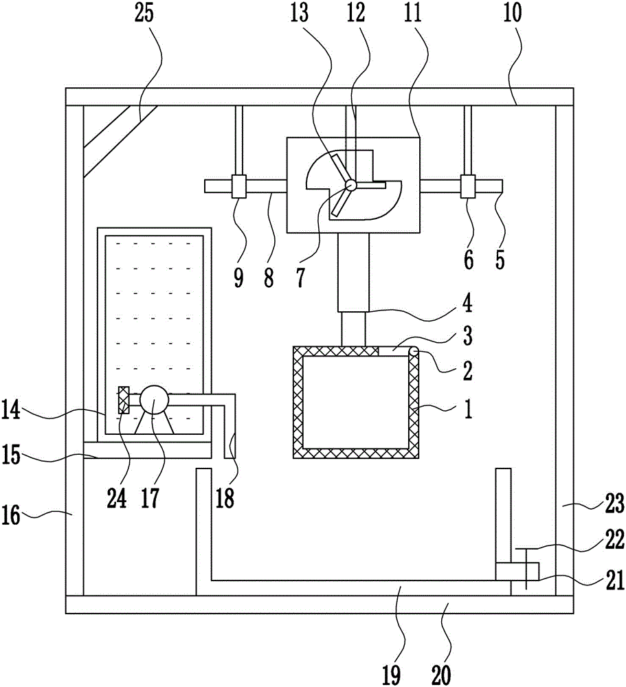
[0028] A kind of high-efficiency cleaning equipment for silicon wafers for silicon solar energy production, such as Figure 1-3 As shown, it includes hollow cleaning box 1, hinge 2, box cover 3, cylinder 4, first guide rod 5, first guide sleeve 6, motor 7, second guide rod 8, second guide sleeve 9, top plate 10 , moving frame 11, bracket 12, rotating rod 13, water tank 14, fixed plate 15, left frame 16, water pump 17, hose 18, cleaning frame 19, bottom plate 20, outlet pipe 21, valve 22 and right frame 23, bottom plate 20 The left frame 16 is welded on the left end of the top, and the fixed plate 15 is welded on the lower right side of the left frame 16. The top of the fixed plate 15 is connected to the water tank 14 by bolt connection, and the water pump 17 is connected to the middle of the bottom of the water tank 14 by bolt connection. 17 is connected with a hose 18 by means of a flange connection, and a cleaning frame 19 is placed on the right side of the top of the bottom...
PUM
 Abstract
Description
Claims
Application Information
 - Generate Ideas
- Intellectual Property
- Life Sciences
- Materials
- Tech Scout
- Unparalleled Data Quality
- Higher Quality Content
- 60% Fewer Hallucinations
Browse by: Latest US Patents, China's latest patents, Technical Efficacy Thesaurus, Application Domain, Technology Topic, Popular Technical Reports.
© 2025 PatSnap. All rights reserved.Legal|Privacy policy|Modern Slavery Act Transparency Statement|Sitemap|About US| Contact US: help@patsnap.com