Antenna ice and snow prevention device

An anti-ice and snow antenna technology, applied in the field of antenna products, can solve the problems of heat loss on the antenna surface, easy condensation of frost, and affecting antenna performance, so as to reduce maintenance costs, save work costs, and improve heating efficiency.

Pending Publication Date: 2017-05-31
GUANGDONG SHENGLU TELECOMM TECH
View PDF3 Cites 5 Cited by
  • Summary
  • Abstract
  • Description
  • Claims
  • Application Information

AI Technical Summary

Problems solved by technology

[0002] At present, the working environment temperature of the antenna is between minus 50 degrees Celsius and minus 75 degrees Celsius, while in areas with high latitudes, the temperature is generally low, and the actual operating temperature is below zero for most of the time of the year; and to avoid the influence of ground buildings or surface shapes For microwave signal transmission, the antenna usually needs to be installed at a very high position, and the wind speed is high, which causes the heat on the surface of the antenna to be quickly lost, and it is very easy to condense frost; once the frost condenses on the surface of the antenna, the electromagnetic wave transmission loss will increase, and the entire system cannot work normally; The higher the frequency, the more obvious the effect of icing on the antenna surface; currently there is no better solution to this problem, only some unconventional means can be used to reduce the effect of ice and snow, such as adding protective devices to the front of the antenna, spraying on the surface Some kind of special coating to prevent frost condensation, etc. This method usually has the disadvantages of affecting the performance of the antenna, short service life, and difficult maintenance.

Method used


Image

  • Antenna ice and snow prevention device
  • Antenna ice and snow prevention device
  • Antenna ice and snow prevention device

Examples


Embodiment Construction

[0015] The technical solution will be described in detail below in conjunction with specific embodiments.

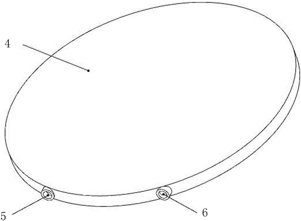
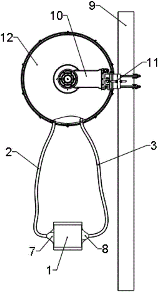
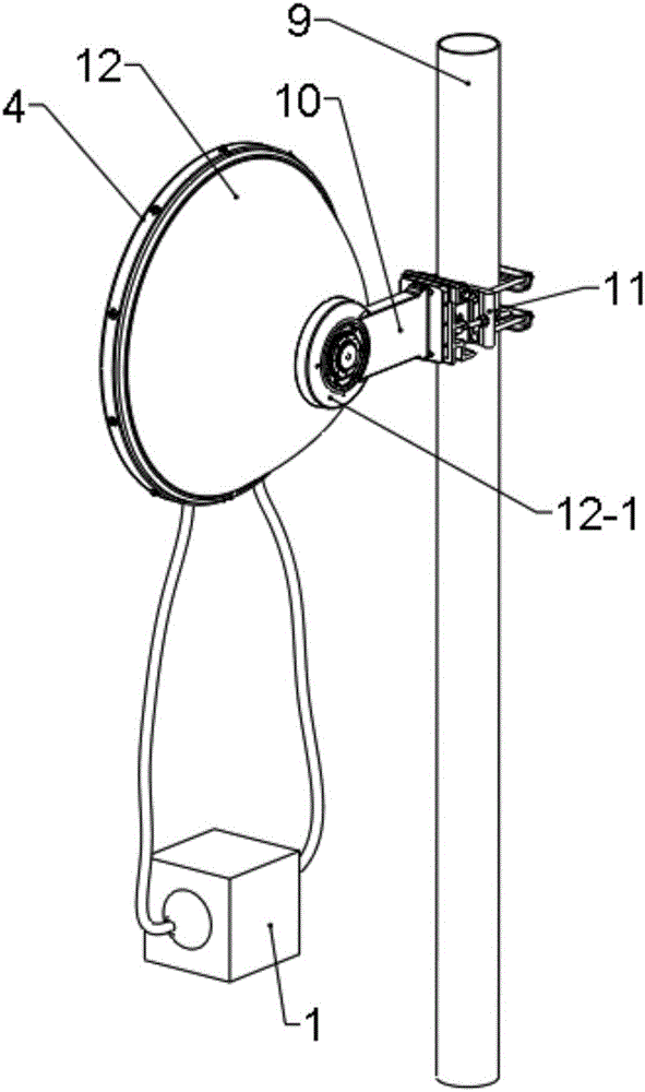
[0016] Such as Figure 1-Figure 3 Shown, the present invention is a kind of anti-icing and snowing device of antenna, and it comprises hot air blower 1 and temperature control system, air intake pipe 2, air outlet pipe 3, cover is established with the radome 4 outside the antenna main body, and temperature control system comprises temperature sensor and Temperature controller, the temperature sensor is set in the radome, connected with the signal input end of the thermostat to monitor the temperature of the radome; the temperature controller is connected to control the hot air blower; there are ventilation channels and radome air intake holes inside the temperature radome 5, the radome air outlet 6, the air outlet 7 of the hot air blower is connected with the air inlet 5 of the radome by the air inlet pipe 2, and the air inlet 8 of the air heater is connected with the ai...


PUM


Abstract

The invention discloses an antenna ice and snow prevention device which is characterized in that the device comprises an air heater, a temperature control system, an air inlet pipeline, an air outlet pipeline and an antenna cover, the antenna cover covers the outside of an antenna body, a ventilation channel, an antenna cover air inlet hole, an antenna cover air outlet hole are formed in the antenna cover, an air outlet of the air heater is connected with the antenna cover air inlet hole through the air inlet pipeline, and an air inlet of the air heater is connected with the antenna cover air outlet hole through the air outlet pipeline, so that a hot air closed-loop recycling system is formed among the antenna cover, the air inlet pipeline, the air outlet pipeline and the air heater. When the temperature is lower than a temperature value set by a temperature control system, the air heater begins to work, the antenna cover is circularly heated, and the surface temperature of the antenna cover is improved. The air heater stops heating when the temperature rises to the temperature value set by the temperature control system. The antenna ice and snow prevention device is simple in structure, convenient to mount and use and more superior in performance as compared with similar products.

Description

technical field [0001] The invention relates to the technical field of antenna products, in particular to an anti-icing device for outdoor antennas. Background technique [0002] At present, the working environment temperature of the antenna is between minus 50 degrees Celsius and minus 75 degrees Celsius, while in areas with high latitudes, the temperature is generally low, and the actual operating temperature is below zero for most of the time of the year; and to avoid the influence of ground buildings or surface shapes For microwave signal transmission, the antenna usually needs to be installed at a very high position, and the wind speed is high, which causes the heat on the surface of the antenna to be quickly lost, and it is very easy to condense frost; once the frost condenses on the surface of the antenna, the electromagnetic wave transmission loss will increase, and the entire system cannot work normally; The higher the frequency, the more obvious the effect of icing...

Claims


Application Information

Patent Timeline
Patent Type & Authority Applications(China)
IPC IPC(8): H01Q1/02H01Q1/42
CPCH01Q1/02H01Q1/42
Inventor 陈志兴庄锦鸿韦谢恩胡奇辉雷佳星
Owner GUANGDONG SHENGLU TELECOMM TECH
Why Eureka
Try Eureka