Series feed microstrip array antenna

A microstrip array and array antenna technology, applied in the field of antennas, can solve the problems of large loss, low power, low gain, etc., and achieve the effects of low loss, improved performance, and low sidelobes

Inactive Publication Date: 2017-05-31
ANHUI SUN CREATE ELECTRONICS
View PDF0 Cites 15 Cited by
  • Summary
  • Abstract
  • Description
  • Claims
  • Application Information

AI Technical Summary

Problems solved by technology

At present, traditional microstrip antennas usually use circular or rectangular patch slots to improve directivity, but the problems of low gain, large loss and low power cannot be solved.

Method used


Image

  • Series feed microstrip array antenna
  • Series feed microstrip array antenna
  • Series feed microstrip array antenna

Examples


Embodiment Construction

[0027] For ease of understanding, the serial-fed microstrip array patch antenna of the 3D traffic management radar system is taken as an example here, and the specific implementation structure and workflow of the present invention are described as follows in conjunction with the accompanying drawings:

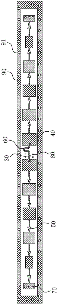
[0028] refer to figure 1 As shown, the serial-fed microstrip array antenna includes twelve microstrip patches 40 of different sizes, a coaxial feeding probe 30, a group of 180° phase shifters 60, and ten groups of triangular gradient linear impedance The matching section 50 and the metal strip 90 arranged around the array antenna. Wherein each microstrip patch 40 of different size is connected through the impedance matching section 50 of triangular gradient line shape of different sizes, and the distance between each adjacent microstrip patch 40 is about 1 / 2 wavelength; The distance between adjacent microstrip patches 40 in this embodiment is 6.5 mm. Twelve microstrip patches...


PUM


Abstract

The invention belongs to the technical field of antennas and particularly relates to a series feed microstrip array antenna which is applicable in a millimeter wave radar system and wireless communication field. The array antenna comprises a medium plate, a paster array antenna and a metal land. An array paster unit is formed by two groups of paster units which are axisymmetrically arranged along axes of feed through holes. Each group of the paster units comprises six microstrip pasters which are successively separately arranged along the length direction of the medium plate and are distributed according to the Chebyshev 25dB amplitude weighting. The interval between adjacent two microstrip pasters in the same paster unit is equal to a half of a wavelength. Every adjacent two microstrip pasters are connected with each other through impedance matching segments in the shape of triangular gradually changed lines. One coaxial feed probe is connected with relatively close microstrip paster on the same group of the paster units through a 180-degree phase shifter. The array antenna is advantaged by high gain, low minor lobe and miniaturization, and requirements of high integration and miniaturization of the whole antenna structure can be effectively achieved.

Description

technical field [0001] The invention belongs to the technical field of antennas, and in particular relates to a series-fed microstrip array antenna applicable to millimeter-wave radar systems and wireless communication fields. Background technique [0002] The antenna is an important radio equipment in the communication system, and its performance will directly affect the performance of the radio equipment. With the continuous development and improvement of wireless communication and radar systems, performance requirements such as light weight, small size, simple fabrication, easy conformality, wide frequency band and low cost have been put forward for antenna performance. Microstrip antennas have attracted people's attention precisely because they meet the above requirements, and their applications have become more and more extensive in recent years. However, the unit gain of the microstrip antenna is generally 6dBi to 8dBi, so the microstrip array antenna composed of micr...

Claims


Application Information

Patent Timeline
Patent Type & Authority Applications(China)
IPC IPC(8): H01Q1/38H01Q1/50H01Q13/08H01Q21/00
CPCH01Q1/50H01Q1/38H01Q13/08H01Q21/00
Inventor 李霞孙浩胡卫东高静侯艳茹袁士涛
Owner ANHUI SUN CREATE ELECTRONICS
Why Eureka
Try Eureka