

Laser polarization state control stabilizing device and control stabilizing method
A technology of stabilizing device and stabilizing method, applied in the field of laser, can solve problems such as complex device, and achieve the effect of short search time
- Summary
- Abstract
- Description
- Claims
- Application Information
AI Technical Summary
Problems solved by technology
Method used
Image

Examples
Embodiment 1
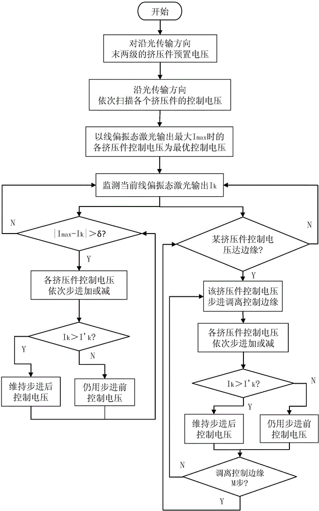
[0054] Embodiment 1 of the method for stabilizing the laser polarization state adopts the embodiment of the above-mentioned laser polarization state stabilization control device, and its flow chart is as follows figure 2 shown, including the following steps:
[0055] Step Ⅰ. Search for the optimal control voltage
[0056] Ⅰ-1. Preset voltage
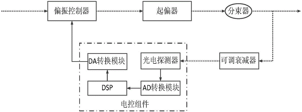
[0057] In this example, the order of the four extrusions of the polarization controller is known, the electric control component presets the voltage -3V to the last two extrusions in the polarization controller along the light transmission direction, and the speed at which the last two extrusions are introduced The phase difference between the axes is 0.45π and 0.55π respectively;
[0058] Ⅰ-2. Control voltage scanning
[0059] In this example, along the direction of light transmission, the control voltage of each extrusion is scanned sequentially. When scanning the control voltage of a certain extrusion, the control voltages of othe...
Embodiment 2
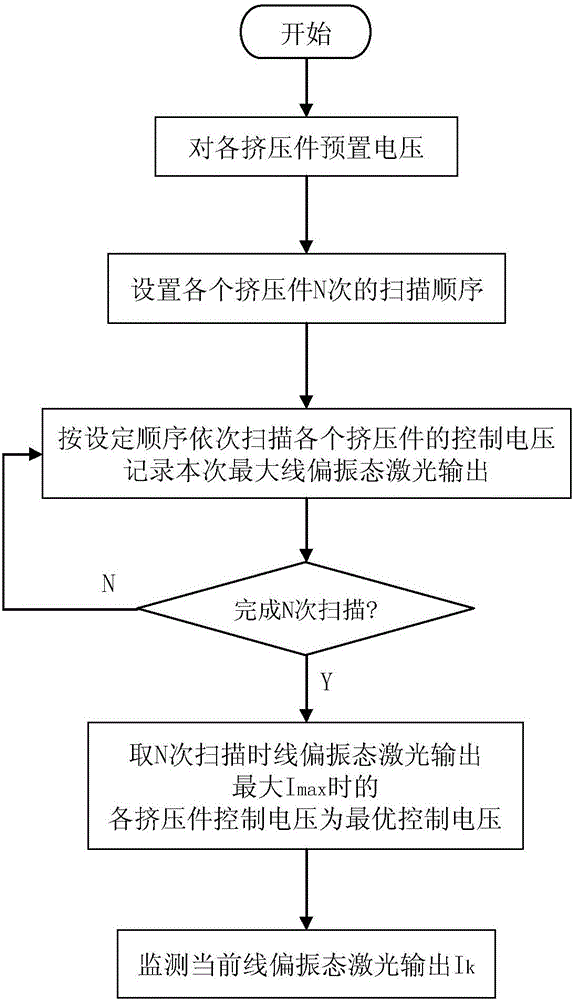
[0073] Embodiment 2 of the method for stabilizing the laser polarization state adopts the above-mentioned embodiment of the laser polarization state stabilization control device, and includes the following steps:
[0074] Step Ⅰ. Search for the optimal control voltage
[0075] The flow chart of this step is as follows image 3 shown.
[0076] Ⅰ-1. Preset voltage
[0077] In this example, the order of the four extrusions of the polarization controller is unknown, and the voltage of each extrusion of the polarization controller is preset at -3V, so that the phase difference between the fast and slow axes introduced by each extrusion is in the range of 0.5π±0.2π Inside.
[0078] Ⅰ-2. Control voltage scanning
[0079] The four extrusions of the polarization controller are respectively numbered 0, 1, 2, and 3, and the number of scans is N=4, and the scan order of the 4 scans is respectively: 0123, 0132, 0213, and 0231. According to the above sequence, the control voltage of ea...
PUM
 Abstract
Description
Claims
Application Information