Dynamic cancellation circuit applicable to output direct-current offset of buck converter

A DC offset and dynamic elimination technology, which is applied in the direction of converting DC power input to DC power output, output power conversion devices, instruments, etc., can solve PWM comparator output jitter, slow system response speed, and decrease loop stability and other problems, to achieve the effect of enhancing system stability, simple control, and increasing precision

Inactive Publication Date: 2017-05-31
UNIV OF ELECTRONIC SCI & TECH OF CHINA
View PDF5 Cites 10 Cited by
  • Summary
  • Abstract
  • Description
  • Claims
  • Application Information

AI Technical Summary

Problems solved by technology

[0003] For the traditional step-down converter, there is a certain compromise in its system performance: the ripple amount superimposed on the positive side of the PWM comparator by the loop is too small, which may cause the decrease of loop stability, and the output jitter of the PWM comparator may cause false triggering and other problems.
If the ripple is too large, the Q value of the system at half the switching frequency will be too low, making the system response slow; and the DC offset introduced by the inherent valley detection mode of the constant turn-on time is too large, which will Under the premise that the buck converter outputs low voltage, it will have a great impact on the system accuracy

Method used


Image

  • Dynamic cancellation circuit applicable to output direct-current offset of buck converter
  • Dynamic cancellation circuit applicable to output direct-current offset of buck converter
  • Dynamic cancellation circuit applicable to output direct-current offset of buck converter

Examples


Embodiment Construction

[0027] Below in conjunction with accompanying drawing, specifically describe the technical scheme of the present invention:

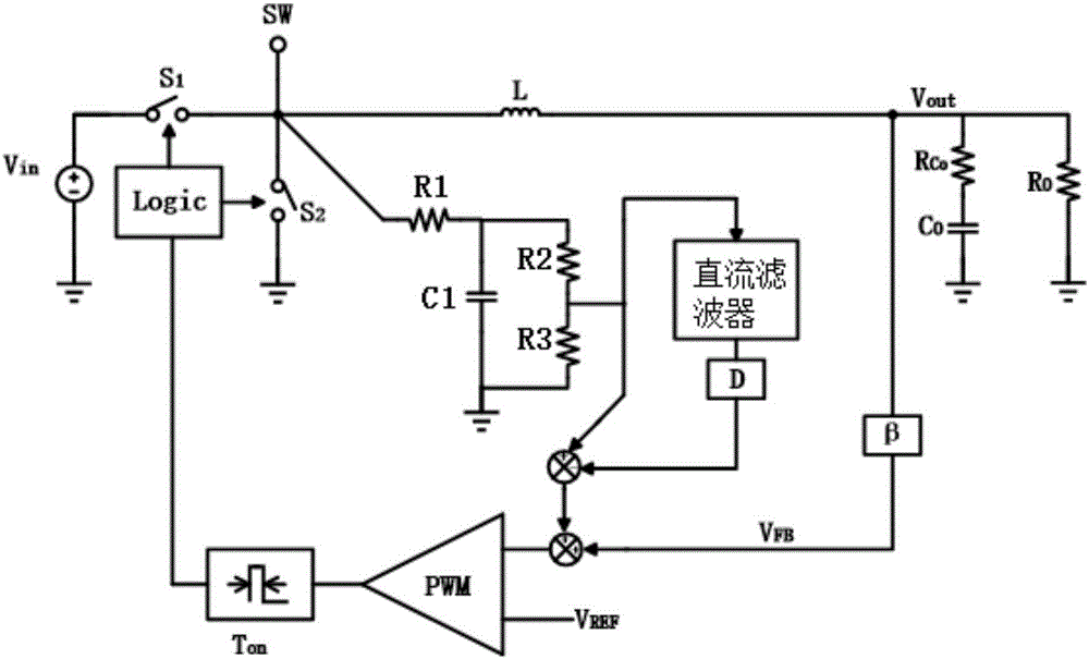
[0028] The present invention proposes a dynamic elimination circuit applicable to the output DC offset of a step-down converter. By adding duty cycle information to a traditional DC filter (DC value extractor), it can be used at different input voltage Vin and output voltage Vout The output DC offset voltage can be dynamically eliminated under different application conditions and different duty cycles, thereby improving the output accuracy of the buck converter; at the same time, the amount of ripple is guaranteed without affecting system stability.

[0029] Such as figure 1 Shown is a principle schematic diagram of a step-down converter based on ripple control applicable to the present invention, wherein the circuit frame is composed of input voltage Vin, inductor L, upper power tube S 1 , lower power tube S 2 , the output capacitor Co and its equiva...


PUM


Abstract

The invention discloses a dynamic cancellation circuit applicable to output direct-current offset of a buck converter and belongs to the technical field of electronic circuits. The dynamic cancellation circuit comprises a ripple generation circuit and a ripple superposition circuit. The dynamic cancellation circuit has the advantages that duty ratio information is added into the ripple generation circuit, voltage at a connection node SW of an upper power tube S1 and a lower power tube S2 is sampled directly to simulate to generate ripples as same as inductive current in phase, and the ripples are superposed on VFB (voltage feedback) to enable the VFB to be equal to preset VREF (voltage reference), so that a PWM (pulse-width modulation) comparator is controlled to overturn normally, system stability is enhanced, the resonance problem caused by output voltage phase lag which results from too small equivalent series resistance of an output capacitor is avoided, output voltage precision of the converter is improved, contradictions between the system stability and the precision of a valley value detection mode under traditional ripple control are overcome, and direct-current offset of output voltage can be dynamically cancelled under different application conditions, namely under different input and output voltages.

Description

technical field [0001] The invention belongs to the technical field of electronic circuits, and in particular relates to a dynamic elimination circuit for DC offset output of a step-down DC-DC converter based on ripple control with constant turn-on time. Background technique [0002] With the wide application of portable electronic devices, the market demand for power management integrated circuits continues to rise, and step-down (Buck) DC-DC converters are widely used in communications, computers, industrial automation and other fields. Traditional step-down DC-DC converters have three control modes, namely current mode, voltage mode and hysteresis control. The Ripple-based Constant On-time Control scheme (Ripple-based Constant On-time Control) is a type of hysteretic mode control, and is widely used due to its simple control, no need for external compensation, excellent load regulation and efficiency, etc. . [0003] For traditional step-down converters, there is a cert...

Claims


Application Information

Patent Timeline
IPC IPC(8): H02M1/14H02M3/157
CPCH02M1/14H02M3/157Y02B70/10
Inventor 明鑫赵佳祎高笛魏秀凌唐韵杨王卓张波
Owner UNIV OF ELECTRONIC SCI & TECH OF CHINA
Why Eureka
Try Eureka