Sterilizing device for pressurized fluid

A technology of pressurized fluid and sterilization device, which is applied in heating methods, lighting and heating equipment, ventilation systems, etc., can solve the problems of sterilization device setting conditions and device miniaturization limitations, and achieve long-term stability and safe use. The device is compact Effect

Inactive Publication Date: 2017-05-31
TOKUYAMA CORP
View PDF22 Cites 5 Cited by
  • Summary
  • Abstract
  • Description
  • Claims
  • Application Information

AI Technical Summary

Problems solved by technology

[0015] However, in the device disclosed in Patent Document 7, since the tank is separately provided in the pressurized air supply line (Patent Document 7 figure 1 7f) in the container, and the ultraviolet germicidal lamp is arranged inside it, therefore, the miniaturization of the device is limited
In addition, the purpose of this device is to prevent the problem that bacteria will be discharged when the device is restarted after a long-term stop. Therefore, the tank needs to be sandwiched in the discharge pipe at the most downstream of the pressurized air supply line. This brings great restrictions to the installation conditions of the sterilization device itself
In addition, there is a problem that when the device starts to work, the pressure surges and the flow rate fluctuates due to the failure of the pressurization system or the damage of the piping, etc., vibration (shock) occurs, and when the ultraviolet germicidal lamp is damaged by this vibration, the mercury Outflow to the outside

Method used


Image

  • Sterilizing device for pressurized fluid
  • Sterilizing device for pressurized fluid
  • Sterilizing device for pressurized fluid

Examples


Embodiment Construction

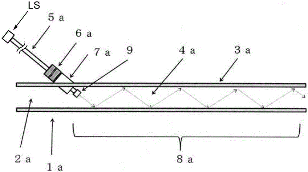
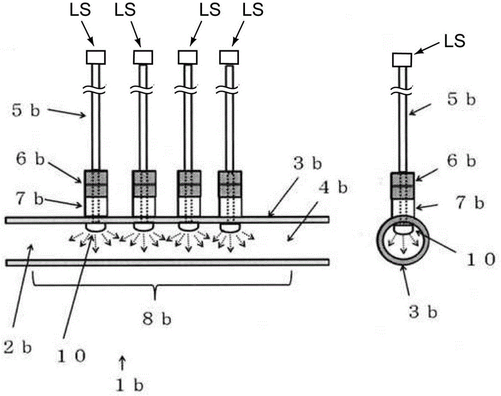
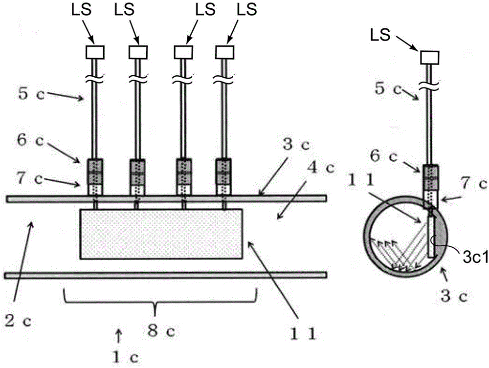
[0027] A pressurized fluid sterilizing device according to an embodiment of the present invention has a pressure-resistant container or piping that defines a pressurized space, and irradiates a pressurized liquid such as a pressurized gas or liquefied gas that exists in the container or piping with ultraviolet rays to sterilize. Sterilization, the pressurized fluid sterilizing device also includes: ""ultraviolet irradiation device", which has an ultraviolet light source and a light transmission mechanism, wherein the light transmission mechanism has a light input port, a light transmission path and a light emission port"; and ""ultraviolet emission The optical component "is arranged in the pressurized space", the ultraviolet light source is arranged outside the pressurized space, and the light emission port is optically connected to the optical component for ultraviolet emission, and the The ultraviolet rays emitted from the light source are transmitted to the ultraviolet emitt...


PUM


Abstract

The invention provides an ultraviolet sterilizing device that can efficiently sterilize a large volume of gas or pressurized liquid with ultraviolet light in a short time and that can be made compact and used safely and stably over a long time. A sterilizing device for pressurized fluid that has a pressure-resistant container or piping that defines a pressurized space and that sterilizes a pressurized fluid such as a pressurized gas or a pressurized liquid present in the container or the piping by irradiating the same with ultraviolet light, wherein said ultraviolet sterilizing device is characterized in that an optical member for ultraviolet light emission such as a diffusing lens or a light guiding plate is disposed in the pressurized space and the ultraviolet light is irradiated onto the pressurized gas or the pressurized liquid present in the pressurized space by the ultraviolet light being emitted from an ultraviolet light source such as a ultraviolet light emitting diode and transmitted to the optical member for ultraviolet light emission by using an optical transmission path such as an optical fiber.

Description

technical field [0001] The invention relates to a pressurized fluid sterilizing device for ultraviolet sterilizing fluid in a pressurized state. More specifically, it relates to a pressurized fluid sterilizing device for irradiating ultraviolet rays to a pressurized fluid, wherein the pressurized fluid is a pressurized gas obtained by pressurizing a gas or a liquefied gas. A pressurized fluid, and a pressurized fluid composed of a pressurized liquid obtained by pressurizing a liquid. Background technique [0002] Ultraviolet light having a wavelength of 200 to 350 nm not only acts on the nucleic acid that is the protoplasm of bacteria to lose its ability to proliferate, but also has the effect of destroying the protoplasm to destroy bacteria. As a light source of such ultraviolet rays, a low-pressure mercury lamp (so-called germicidal lamp) that emits light of a wavelength of 253.7 nm (resonance of mercury) generated by discharge of mercury vapor at a low pressure (about 0....

Claims


Application Information

Patent Timeline
Patent Type & Authority Applications(China)
IPC IPC(8): A61L2/10A61L9/20A61N5/06C02F1/32F24F7/00
CPCA61N5/06A61L2/10C02F1/32A61L2202/11A61L2202/122A61L2209/13A61L9/20C02F1/325A61L2209/134A61L2209/14F24F8/22A61L2209/12
Inventor 松井新吾堀井百合子山本玲绪弘中启一郎滨康孝
Owner TOKUYAMA CORP
Why Eureka
Try Eureka