Air purification device

An air purification device and air flow path technology, applied in chemical instruments and methods, separation methods, dispersed particle separation, etc., can solve the problems of difficult oil mist electrification, mounting multiple differential pressures, etc., to ensure stability and simplify removal. effect of the process

Active Publication Date: 2017-05-31
LG ELECTRONICS INC +1
View PDF6 Cites 1 Cited by
  • Summary
  • Abstract
  • Description
  • Claims
  • Application Information

AI Technical Summary

Problems solved by technology

[0006] According to the previous patent, when a high voltage is applied, it is difficult to effectively charge the oil mist flowing at a relati

Method used


Image

  • Air purification device
  • Air purification device
  • Air purification device

Examples


Embodiment Construction

[0038] Hereinafter, embodiments disclosed in this specification will be described in detail with reference to the accompanying drawings. Herein, the same or similar structural elements will be assigned the same reference numerals regardless of the reference numerals, and repeated description thereof will be omitted. The suffixes "module" and "part" used in the following descriptions for structural elements are given or used in combination only for the convenience of writing the description, and do not have mutually distinguishing meanings or functions. In addition, in the process of describing the embodiments disclosed in the present invention, if it is judged that the specific description of related known technologies will lead to confusion of the technical ideas of the embodiments disclosed in this specification, the detailed description will be omitted. Moreover, the attached drawings are only for easy understanding of the embodiments disclosed in this specification, and the...


PUM


Abstract

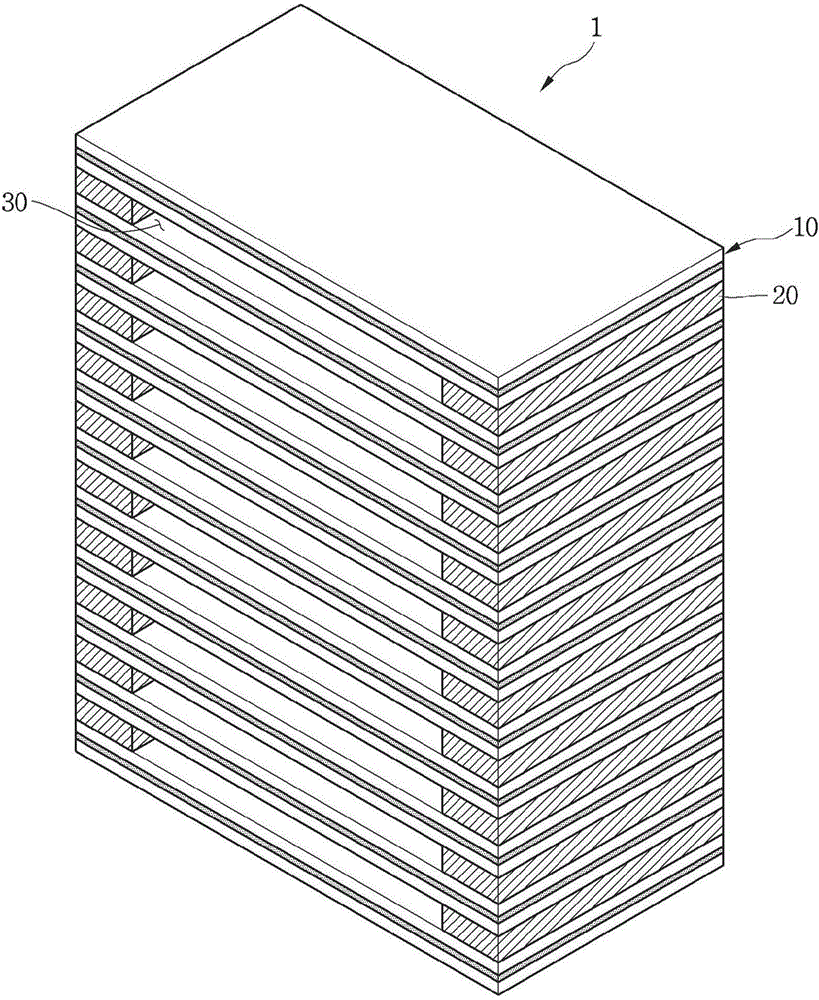
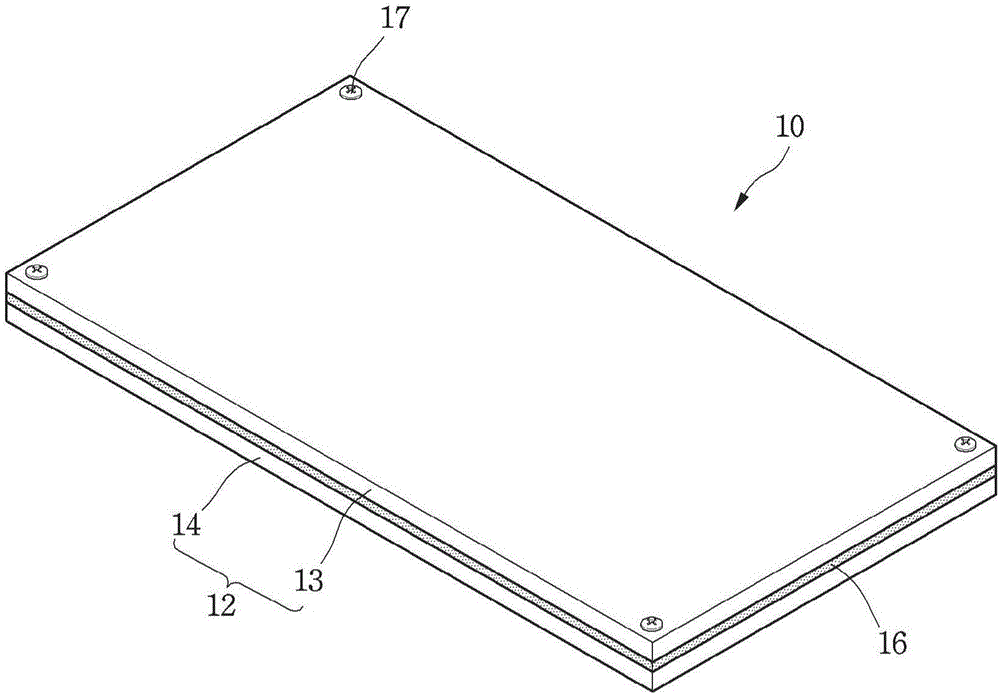
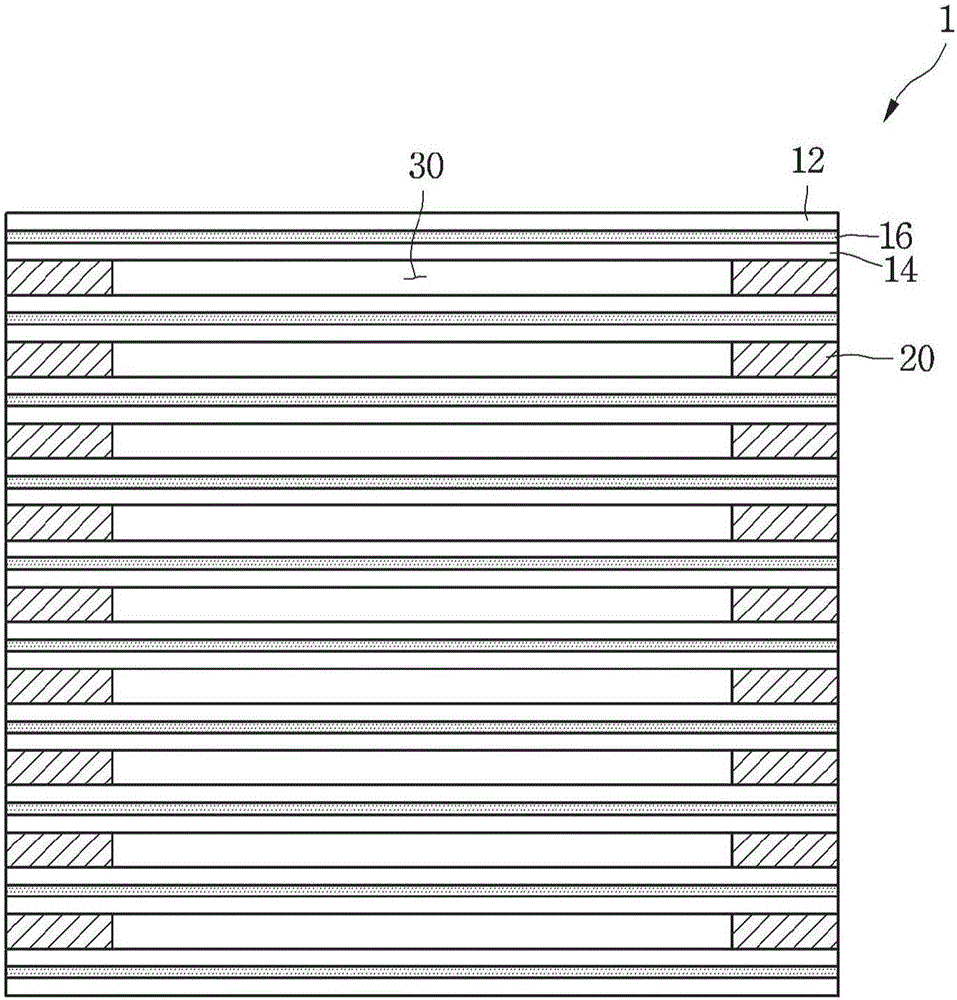
The present invention relates to an air purification device. An air purification device, according to an embodiment, comprises: a plurality of electrode modules which are provided on an air flow path; and a support portion which forms a space portion between the plurality of electrode modules by having the plurality of electrode modules positioned away from each other, wherein the electrode modules have electrode portions, to which a voltage is applied and which form a plasma region, and a dielectric body which is placed on one or more sides of the electrode portions and collects contaminant in the air.

Description

technical field [0001] The present invention relates to an air cleaning device. Background technique [0002] Oil mist is an organic compound contained in the fumes produced during the cooking of food. The oil mist exists in the liquid phase or in the state of fine particles in the high-temperature area and is easy to handle. However, in the low-temperature area, it is attached and fixed to the surface or wall of the ventilation device due to its viscosity, thereby reducing the device's efficiency. Function, in severe cases, will become a factor causing device paralysis. [0003] In particular, oil mist will be discharged in higher concentrations during cooking of meat. The oil mist discharged during the cooking of meat will react with oxygen, water vapor, etc. in the air, thereby being hardened or turned into solid particles. Such fine particles in a solid state stick to the interior of the ventilator, and the blocks formed by it will gradually become larger, thereby red...

Claims


Application Information

Patent Timeline
IPC IPC(8): B03C3/40B03C3/34B01D53/32
CPCB01D53/32B03C3/34B03C3/40
Inventor 朴哲佑李成华崔智恩黄正皓
Owner LG ELECTRONICS INC
Why Eureka
Try Eureka