Method of measuring plane stress of anisotropic material

A technology of plane stress and anisotropy, applied in the direction of measuring force, measuring device, instrument, etc., can solve the problem of low measurement accuracy

Active Publication Date: 2017-06-06
太原源瀚科技有限责任公司
View PDF8 Cites 10 Cited by
  • Summary
  • Abstract
  • Description
  • Claims
  • Application Information

AI Technical Summary

Problems solved by technology

[0004] The present invention aims to solve the problem of low measurement accuracy of existing stress detection methods. Based on the principle of critical ref

Method used


Image

  • Method of measuring plane stress of anisotropic material
  • Method of measuring plane stress of anisotropic material
  • Method of measuring plane stress of anisotropic material

Examples


specific Embodiment approach 1

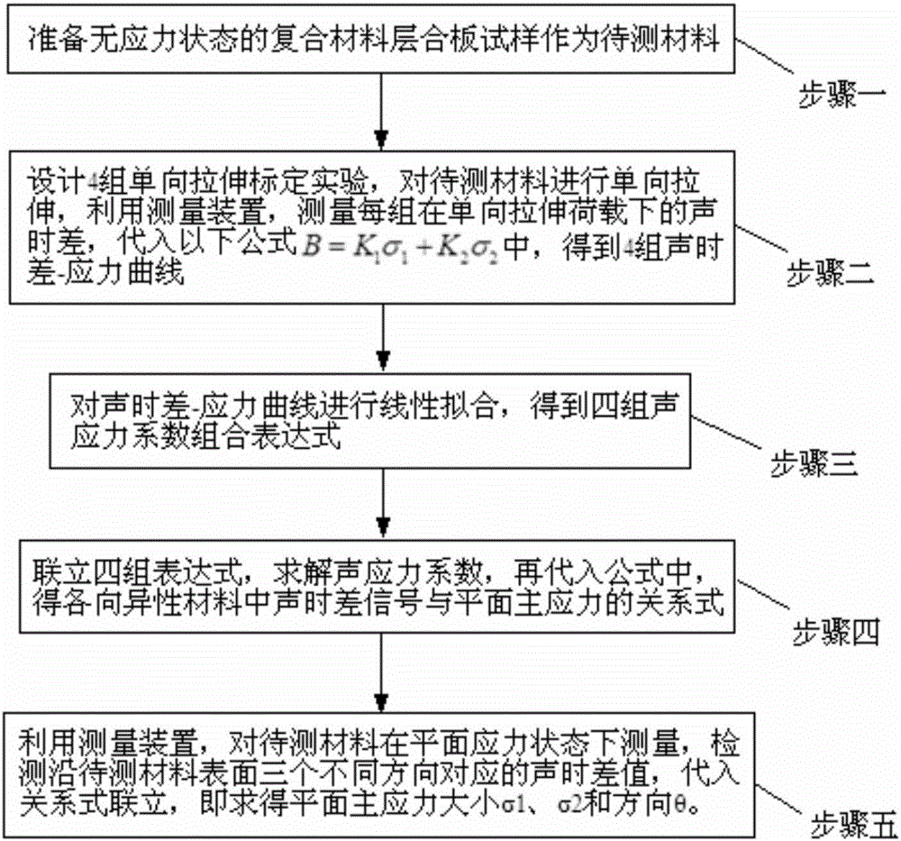
[0057] Embodiment 1: The method for measuring the plane stress of anisotropic materials in this embodiment includes the following steps:

[0058] 1. Prepare a composite laminate sample in an unstressed state as the material to be tested;

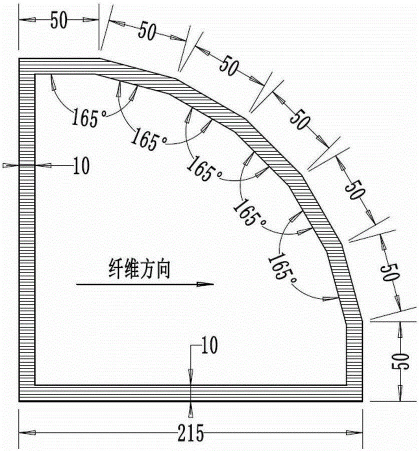
[0059] 2. Design 4 sets of unidirectional tensile calibration experiments, select 4 sets of calibration directions, and perform uniaxial stretching on the material to be tested. Use the device for measuring the plane stress of anisotropic materials to measure the sound of each group under unidirectional tensile load. The time difference is substituted into the following formula to obtain 4 sets of acoustic time difference-stress curves respectively;

[0060] B=K 1 σ 1 +K 2 σ 2 ,

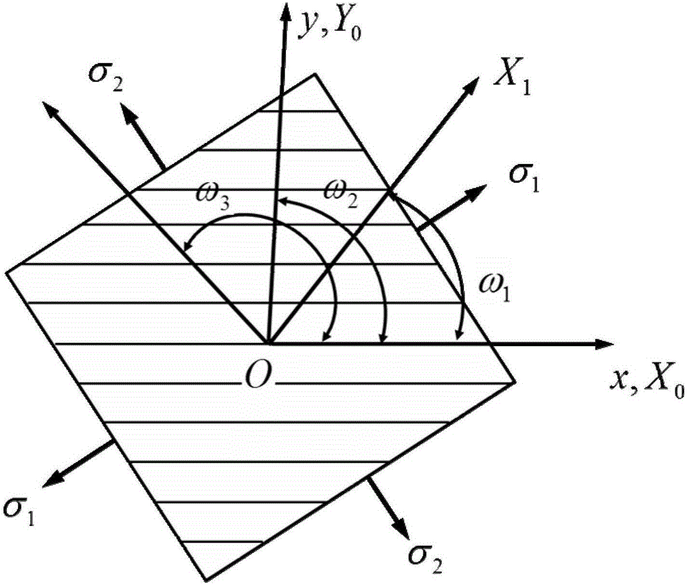
[0061] where K 1 =m 1 (cos2θ+cos2ω)+m 2 +m 3 cos2θcos2ω+m 4 sin2θsin2ω,

[0062] K 2 =-m 1 (cos2θ-cos2ω)+m 2 -m 3 cos2θcos2ω-m 4 sin2θsin2ω

[0063] B is the acoustic time difference of the detection signal, σ 1 is the first principal stress of th...

specific Embodiment approach 2

[0069] Specific implementation mode two: the difference between this implementation mode and specific implementation mode one is: combining Figure 5 To illustrate this embodiment, the device for measuring the plane stress of anisotropic materials includes an ultrasonic transducer group, an ultrasonic oblique incidence wedge 2, a signal generator 3, a digital oscilloscope 4, and an analysis and processing software 5;

[0070] The shape of the ultrasonic oblique incidence wedge 2 is a regular octagon, and the oblique incidence angle is 34°;

[0071] The ultrasonic transducer group includes a first ultrasonic longitudinal wave excitation probe 11, a second ultrasonic longitudinal wave excitation probe 12, a third ultrasonic longitudinal wave excitation probe 13, a first ultrasonic longitudinal wave receiving probe 14, a second ultrasonic longitudinal wave receiving probe 15 and a third ultrasonic longitudinal wave receiving probe 15. Ultrasonic longitudinal wave receiving probe ...

specific Embodiment approach 3

[0076] Embodiment 3: This embodiment is different from Embodiment 2 in that: the ultrasonic oblique incidence wedge 2 is made of polytetrafluoroethylene. Others are the same as in the second embodiment.


PUM


Abstract

A method of measuring plane stress of an anisotropic material relates to a measuring method of plane stress of a material and is aimed at solving the problem that a conventional stress detection method is not high in measuring precision. The method includes the following steps: firstly, preparing a material to be measured; secondly, designing four unidirectional stretching calibration experiments, and obtaining four sound time difference-stress curves; thirdly, conducting linear fitting on the four sound time difference-stress curves, and obtaining four sound stress coefficient combination expressions and values; fourthly, conducting simultaneous equations on the four expressions, that is to say, obtaining a relation between sound time difference signals and plane main stress; and fifthly, utilizing a measuring device to measure the material to be measured in a plane stress state, detecting sound time difference values in three different directions respectively, conducting substitute-type simultaneous equations, and thus obtaining the magnitude [sigma]1 and [sigma]2 and the direction [theta] of plane main stress. The method, based on the critical refraction longitudinal wave principle, is easy to operate, is high in efficiency, is suitable for all anisotropic materials, and can be widely applied to detection and analysis of plane stress of composite material laminated boards in the field of aerospace, weapon manufacture, vehicles, etc.

Description

technical field [0001] The invention relates to a method for measuring plane stress of a material. Background technique [0002] At present, the measurement of stress state in materials can be roughly divided into two categories: lossy and nondestructive. Compared with destructive methods, non-destructive methods do not cause irreversible damage to the material under test, so they have unique advantages. Among the non-destructive methods, the ultrasonic method has obvious advantages in many non-destructive testing methods due to its advantages of high efficiency, reliability, safety and portability, and its development is particularly rapid. [0003] Traditional ultrasonic testing methods are all developed on the premise that the material to be tested is isotropic, that is, anisotropy such as material inhomogeneity and texture orientation are ignored. For the current commonly used materials, anisotropy is ubiquitous, and they more or less affect the detection accuracy of t...

Claims


Application Information

Patent Timeline
IPC IPC(8): G01L1/25
CPCG01L1/255
Inventor 张宇民王伟周玉锋姚泰董善亮陈栋康康周小琳王道畅吕汉雄
Owner 太原源瀚科技有限责任公司
Why Eureka
Try Eureka