
Method for eliminating electrostatic charge, and substrate unloading method

An electrostatic charge and substrate technology, applied in the field of microelectronics, can solve the problems of chip top, economic loss, hardware damage, etc., and achieve the effect of low cost and safe operation

Active Publication Date: 2017-06-09
BEIJING NAURA MICROELECTRONICS EQUIP CO LTD
View PDF3 Cites 6 Cited by
  • Summary
  • Abstract
  • Description
  • Claims
  • Application Information

AI Technical Summary

Problems solved by technology

the above Figure 3a and Figure 3b Any of the above situations is undesirable, especially for automatic production, the chip sticking will not only cause the substrate to be crushed by the lifting pin 21, but also cause the manipulator 22 to hit the substrate S, which will cause economic losses and Hardware damage must be avoided

Method used


Image

  • Method for eliminating electrostatic charge, and substrate unloading method
  • Method for eliminating electrostatic charge, and substrate unloading method
  • Method for eliminating electrostatic charge, and substrate unloading method

Examples


Embodiment Construction

[0032] In order to enable those skilled in the art to better understand the technical solution of the present invention, the method for eliminating static charge and the substrate unloading method provided by the present invention will be described in detail below with reference to the accompanying drawings.

[0033] Figure 4 A flow chart of a method for eliminating static charges provided by an embodiment of the present invention. see Figure 4 , the method for eliminating static charge that the embodiment of the present invention provides, comprises the following steps:

[0034] S1, blowing the first gas to the back of the substrate so that there is a gap between the substrate and the electrostatic chuck, and at the same time introducing a second gas into the chamber to excite the second gas to form plasma.

[0035] Specifically, the first gas and the second gas are generally selected from gases that do not affect the substrate, for example, inert gases. In this embodime...


PUM


Abstract

The invention provides a method for eliminating electrostatic charges, and a substrate unloading method. The method for eliminating electrostatic charges comprises the steps of: blowing a first gas to the back surface of a substrate so that a gap exists between the substrate and an electrostatic chuck; and introducing a second gas into a chamber and activating the second gas to form plasma. The method for eliminating electrostatic charges and the substrate unloading method provided by the invention can ensure that substrate bonding cannot occur in subsequent substrate unloading, thereby preventing the substrate from being crushed due to substrate bonding or smashed by a mechanical arm when the substrate is inclined, and ensuring the reliable and safe operation of the substrate unloading process.

Description

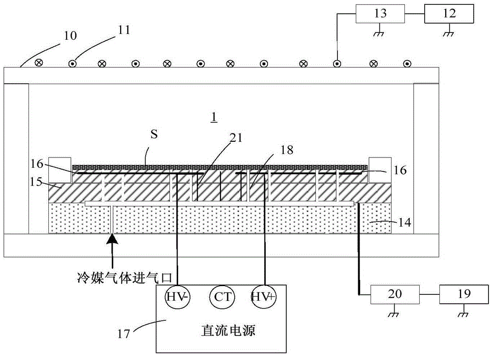
technical field [0001] The invention belongs to the technical field of microelectronics, and relates to a method for eliminating static charges and a substrate unloading method. Background technique [0002] Semiconductor processing equipment such as plasma etching equipment, physical vapor deposition equipment, and chemical vapor deposition equipment often use electrostatic chucks to support and fix the substrate, and to control the temperature of the substrate. [0003] figure 1 For a schematic diagram of a typical reaction chamber, see figure 1 An inductively coupled coil 11 is arranged above the dielectric window 10 at the top of the reaction chamber 1, and an upper excitation radio frequency power supply 12 is electrically connected to the inductively coupled coil 11 through an upper matching device 13 to form an upper electrode for exciting the process gas in the chamber. Plasma is formed; a base 14 is provided in the reaction chamber 1, and an electrostatic chuck 15...

Claims


Application Information

Patent Timeline
Patent Type & Authority Applications(China)
IPC IPC(8): H01L21/683H01L21/02
CPCH01L21/02H01L21/683
Inventor 李玉站
Owner BEIJING NAURA MICROELECTRONICS EQUIP CO LTD
Learn More