
Neutral-point balance circuit applied to half-bridge three-level DC converter and control method thereof

A technology of balancing circuits and converters, which is applied in the direction of converting DC power input to DC power output, adjusting electrical variables, and controlling/regulating systems, etc., which can solve problems such as increased hardware costs, reduced system reliability, and high hardware costs, and achieve reduction Circuit size and cost, easy engineering implementation, eliminating the effect of DC blocking capacitors

Active Publication Date: 2017-06-09
合肥博鳌电气科技有限公司
View PDF1 Cites 7 Cited by
  • Summary
  • Abstract
  • Description
  • Claims
  • Application Information

AI Technical Summary

Problems solved by technology

Its shortcoming is that although the general method of midpoint balance of non-isolated three-level converters is introduced in this paper, this interleaved control circuit uses a single-edge triggered dual-carrier modulation method, which increases hardware costs, and its adjustment method lack of freedom of control
[0006] Literature "Weiyang Zhou, Xiaoyang Yu, Ke Jin, Zhijun Liu. Capacitor voltage control strategy for half-bridge three-level DC converter [J]. Journal of Electrotechnical Society, 2015, 30(16). "In this paper, two controlled quantities are used, and a This dual-edge modulation strategy realizes the capacitive voltage equalization control of the four-switch half-bridge three-level DC converter, but its dual-edge trigger mode is realized based on the same modulation wave, and the phase shifting function cannot be realized.
In order to achieve phase shift control, the patent increases the analog control part, resulting in lower system reliability and higher cost
[0007] To sum up, at present, analog circuit control is mainly used to deal with the midpoint balance problem of half-bridge three-level topology at home and abroad, but analog control has limitations such as low control accuracy, small control degree of freedom, and high hardware cost.

Method used


Image

  • Neutral-point balance circuit applied to half-bridge three-level DC converter and control method thereof
  • Neutral-point balance circuit applied to half-bridge three-level DC converter and control method thereof
  • Neutral-point balance circuit applied to half-bridge three-level DC converter and control method thereof

Examples


Embodiment Construction

[0044] Below in conjunction with accompanying drawing, the present invention is described in further detail:

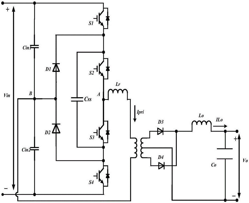
[0045] Such as figure 1 As shown, a mid-point balance circuit for a half-bridge three-level DC converter of the present invention mainly includes a DC bus, a half-bridge three-level main circuit, and a capacitor C in1 with C in2 (upper and lower voltage divider capacitors), flying capacitor C ss , clamping diode D 1 with D 2 , and its specific topology is as follows: the total DC bus voltage V in , the voltage dividing capacitor C connected in series on the DC side in1 and C in2 , capacitance C in1 The positive pole of the DC bus is connected to the positive pole of the capacitor C in1 The negative pole and the capacitor C in2 The positive connection of the converter is defined as the midpoint B of the converter, and the capacitor C in2 The negative pole of the DC bus is connected to the negative pole of the DC bus. The topology of the half-bridge three-lev...


PUM


Abstract

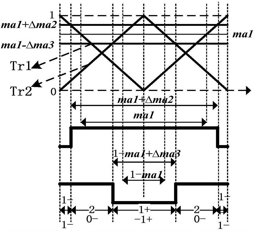
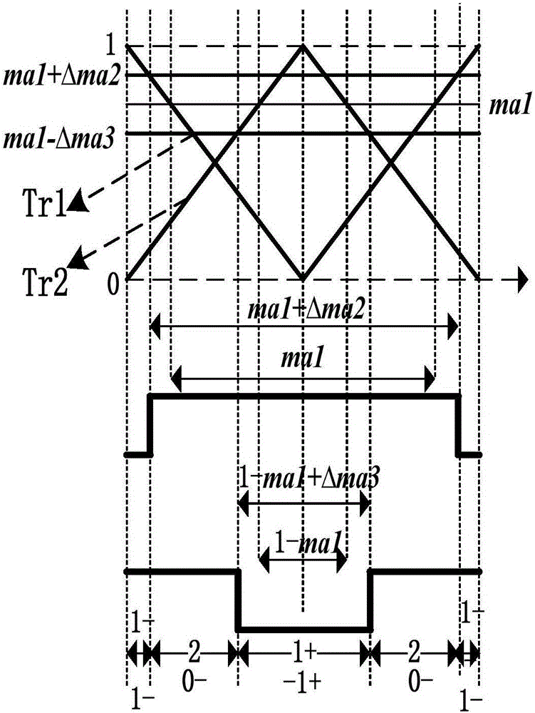
The invention discloses a neutral-point balance circuit applied to a half-bridge three-level DC converter; the neutral-point balance circuit mainly comprises a DC bus, a half-bridge three-level main circuit, capacitors Cin1 and Cin2, a flying capacitor Css, clamping diodes D1 and D2, and an output circuit; the invention also discloses a control method based on said circuit; the method uses up-down voltage dividing capacitance voltage difference formed by drive circuit and switch tube characteristic differences in system real operations to correct modulated waves, thus realizing the voltage dividing capacitance voltage sharing digital control method, and effectively solving the neutral-point imbalance problems caused by drive chip and switch tube characteristic differences in a conventional half-bridge three-level circuit; the neutral-point balance circuit and control method thereof are fast in response speed, and high in control precision.

Description

technical field [0001] The invention belongs to the technical field of power electronics, and in particular relates to a midpoint balance circuit for realizing a half-bridge three-level DC converter and a corresponding digital control method. Background technique [0002] In recent years, half-bridge three-level DC converters have been widely used in high-voltage DC transmission, locomotive traction and other fields, breaking through the voltage level limitations of existing power devices such as IGBTs, and are currently a hot research topic in the field of power electronics DC conversion. one of the subjects. [0003] In the half-bridge three-level DC converter, two switching tubes are connected in series to replace one switching tube in the traditional half-bridge converter, and the flying capacitor plays the role of decoupling the soft switching process of the leading arm and the lagging arm and the voltage equalizing switching tube. , and the clamping diode not only hel...

Claims


Application Information

Patent Timeline
IPC IPC(8): H02M3/335
CPCH02M3/33515
Inventor 何立灿
Owner 合肥博鳌电气科技有限公司
Learn More