Lifting hook type shot blasting machine

A shot blasting machine and hook technology, which is applied in the manufacturing field, can solve the problem that loading and unloading cannot be carried out at the same time, and achieve the effect of remarkable strengthening effect, easy maintenance and low noise.

Inactive Publication Date: 2017-06-13
青岛纵横农业科技有限公司
View PDF0 Cites 1 Cited by
  • Summary
  • Abstract
  • Description
  • Claims
  • Application Information

AI Technical Summary

Problems solved by technology

[0003] The present invention overcomes the deficiencies of the prior art and proposes a hook-type shot blasting machine. The hook of the cleaning machine is integrated with the turntable, which solves the problem that the previous cleaning equipment cannot be loaded and unloaded at the same time, and improves the efficiency.

Method used


Image

  • Lifting hook type shot blasting machine
  • Lifting hook type shot blasting machine
  • Lifting hook type shot blasting machine

Examples


Embodiment Construction

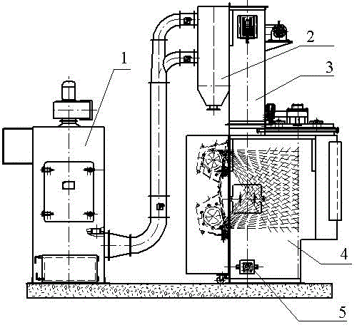
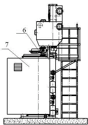
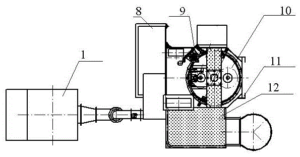
[0024] see Figure 1 to Figure 5 As shown, the present invention comprises a cleaning room 4, an electric control system, a dust collector 1, a separator 2, a hoist 3, a pill feeding system 6, and a screw conveying system 5, and the electric control system is responsible for the control and operation of the entire system, and the cleaning A hook turntable mechanism is provided in the chamber 4, and the screw conveying system 5 is located at the bottom of the cleaning chamber 4, and a hoist 3 is arranged on the side of the cleaning chamber 4, and a separator 2 is arranged on the side of the hoist 3, so that The separator 2 is connected with the dust collector 1 through a closed pipe, and a shot supply system 6 is provided on one side of the hook turntable mechanism. One shot blasting machine, two shot blasting machines are fixed on the switch type shot blasting door 7 at the rear of the chamber body, when the switch type shot blasting door 7 is opened and closed, the shot blast...


PUM


Abstract

The invention relates to a hook-type shot blasting machine, which includes a cleaning room, an electric control system, a dust collector, a separator, a hoist, a shot feeding system, a switch type shot blasting door, and a screw conveying system. hook turntable mechanism and two shot blasters, the screw conveying system is located in the lower part of the cleaning room, a lifter is provided on the side of the cleaning room, and a separator is provided on the side of the lifter, and the separator passes through the airtight The pipeline is connected with the dust collector. A shot feeding system is installed on one side of the hook turntable mechanism. The switch type shot blasting door is set under the shot feeding system. The other side of the mechanism is equipped with a noise reduction safety guard.

Description

technical field [0001] The invention belongs to the field of manufacturing technology, and in particular relates to a hook type shot blasting machine. Background technique [0002] The separation device is a part of the stainless steel belt shot blasting machine. The general separation device requires a longer sorting area, larger volume and higher cost. However, the longer the separation area is, the more difficult it is for the actual flow curtain to form a full curtain, and the greater the separation air volume is consumed, but the separation efficiency is not ideal, and the separation air volume cannot be effectively utilized, and it is easy to form a thick curtain at the sand inlet. , the pellets cannot be effectively separated, and the curtain is very thin or even has no pellets at the far inlet sand port, and the air volume cannot be effectively utilized. Contents of the invention [0003] The present invention overcomes the deficiencies of the prior art and propos...

Claims


Application Information

Patent Timeline
Patent Type & Authority Applications(China)
IPC IPC(8): B24C3/02B24C9/00
CPCB24C3/02B24C9/00
Inventor 不公告发明人
Owner 青岛纵横农业科技有限公司
Why Eureka
Try Eureka