Low and ultra-low permeable reservoir CO2 drive near-miscible pressure area determining method

A technology of miscible pressure and area determination, which is applied in earth-moving drilling, wellbore/well components, and production fluids, etc., can solve the problems of unclear judgment and understanding of near-miscible flooding conditions, and achieve the effect of true and reliable measurement results.

Active Publication Date: 2017-06-13
CHINA UNIV OF PETROLEUM (BEIJING)
View PDF6 Cites 18 Cited by
  • Summary
  • Abstract
  • Description
  • Claims
  • Application Information

AI Technical Summary

Problems solved by technology

[0005] Although the concept of near-miscible flooding was put forward earlier, in recent years CO 2 Near-miscible flooding has attracted more and more attention from domestic and foreign scholars, and domestic and foreign scholars have also conducted a

Method used


Image

  • Low and ultra-low permeable reservoir CO2 drive near-miscible pressure area determining method
  • Low and ultra-low permeable reservoir CO2 drive near-miscible pressure area determining method
  • Low and ultra-low permeable reservoir CO2 drive near-miscible pressure area determining method

Examples


Embodiment 1

[0058] In this embodiment, according to the mineral composition of formation water and injection water in the target block, the formation water and injection water in the target oilfield block are used to prepare simulated water-based injection water for the experiment. The total salinity of the water is 80063.14mg / L, The hardness is 4905.79mg / L; according to the well fluid composition of the sampling well in the target oilfield block, the degassed and dehydrated crude oil in the target oilfield block is mixed with hydrocarbon gas in a certain proportion to prepare simulated oil, and the simulated oil viscosity is 2.38mPa·s ; using high-purity CO 2 As the injected gas, the purity of the gas is 99.99%; the formation temperature of the target oilfield block is 60°C.

[0059] Adopt a kind of low, ultra-low permeability reservoir CO of the present invention 2 A method for determining the area of ​​near-miscible pressure during flooding, and determining the CO content of the targe...

Embodiment 2

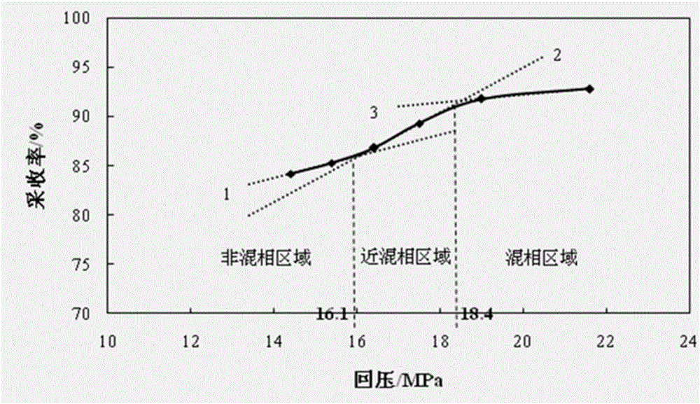
[0075] In the present embodiment, adopt the method of the present invention to determine the CO 2 When driving close to the miscible pressure area, the size of the physical model core used is 50×4.5×4.5cm 3 ;Other experimental conditions, experimental materials and concrete steps are basically the same as in Example 1, and CO under different displacement pressures and back pressure conditions is obtained. 2 The specific experimental results are shown in Table 2; the CO 2 The relationship curve between flooding recovery and back pressure, such as Figure 4 shown.

[0076] Table 2 50cm long core CO 2 The relationship between flooding recovery and back pressure (20×10 -3 μm 2 )

[0077]

[0078] It can be seen from Table 2 that the physical properties of the low-permeability core reservoirs in each experimental group are roughly the same, and the gas permeability is 20×10 -3 μm 2 , the core porosity is between 15% and 19%, and the original oil saturation is between 33%...

Embodiment 3

[0083] In the present embodiment, adopt the method of the present invention to determine the CO 2 When driving close to the miscible pressure area, the size of the physical model core used is 80×4.5×4.5cm 3 ;Other experimental conditions, experimental materials and concrete steps are basically the same as in Example 1, and CO under different displacement pressures and back pressure conditions is obtained. 2 The specific experimental results are shown in Table 3; the CO 2 The relationship curve between flooding recovery and back pressure, such as Figure 5 shown.

[0084] Table 3 80cm long core CO 2 The relationship between flooding recovery and back pressure (20×10 -3 μm 2 )

[0085]

[0086] It can be seen from Table 3 that the physical properties of the low-permeability core reservoirs in each experimental group are roughly the same, and the gas permeability is 20×10 -3 μm 2 , the core porosity is between 14% and 18%, and the original oil saturation is between 36%...


PUM

PropertyMeasurementUnit
Core permeabilityaaaaaaaaaa
Total salinityaaaaaaaaaa
Gas permeabilityaaaaaaaaaa

Abstract

The invention relates to a low and ultra-low permeable reservoir CO2 drive near-miscible pressure area determining method. The method includes: 1), selecting and pre-processing a physical model core; 2), adding circling pressure and performing vacuum pumping; 3), measuring pore volume and calculating porosity; 4), heating to target strata temperature and performing water measurement on permeability; 5), simulating saturated-oil process and calculating initial oil saturation; 6), simulating CO2 displacement and calculating CO2 drive recovery rate; 7), repeating the steps 1) to 6) to acquire the CO2 drive recovery rate under different displacement pressure and back pressure conditions; 8), drawing a relation curve of the CO2 drive recovery rate and back pressure; 9), according to rate of the curve, dividing the CO2 drive into three phases of the immiscible phase, near-miscible phase and miscible phase to acquire a trend line of the relation curve of the immiscible phase, near-miscible phase and miscible phase CO2 drive recovery rate and back pressure; 10), determining the low and ultra-low permeable reservoir CO2 drive near-miscible pressure area according to the intersection of the immiscible phase and the near-miscible phase and the intersection of the near-miscible phase and the miscible phase.

Description

technical field [0001] The invention belongs to low permeability reservoir CO 2 In the field of flooding development technology, especially a kind of low and ultra-low permeability reservoir CO 2 A method for determining the approaching miscibility pressure region. Background technique [0002] Many scholars at home and abroad have shown that among many methods of enhancing oil recovery, CO 2 EOR technology occupies an important position, and CO2 is used in the United States and Canada 2 Enhanced oil recovery by flooding has achieved great success. And with my country's CO 2 The continuous discovery of gas sources and the CO 2 The maturity of the capture technology, in my country's CO 2 Flooding technology will also become a cost-effective enhanced oil recovery technology. [0003] CO 2 Flooding technology can be divided into immiscible flooding, near-miscible flooding and miscible flooding according to the mechanism of enhanced oil recovery. Among them, CO 2 Immis...

Claims


Application Information

Patent Timeline
IPC IPC(8): E21B43/16E21B47/06
CPCE21B43/164E21B47/06
Inventor 侯吉瑞郝宏达赵凤兰李文峰付忠凤侯利斌王志兴
Owner CHINA UNIV OF PETROLEUM (BEIJING)
Why Eureka
Try Eureka