Motor carbon brush sintering furnace

A sintering furnace and carbon brush technology, applied in furnaces, crucible furnaces, furnace types, etc., can solve the problems of waste heat, atmospheric environment impact, reduction of furnace sintering temperature, etc., to reduce pollution, ensure sintering quality, and reduce waste. Effect

Active Publication Date: 2018-10-30
CHONGQING HEHAI CARBON PROD
View PDF3 Cites 0 Cited by
  • Summary
  • Abstract
  • Description
  • Claims
  • Application Information

AI Technical Summary

Problems solved by technology

[0004] The above scheme discharges the dense smoke generated during sintering through the inert gas introduced, which improves the qualified rate of the product, but there are still the following problems: the inert gas is continuously filled, and the inert gas can squeeze the generated dense smoke to the exhaust On the one hand, due to the low temperature of the inert gas, it will exchange heat with the furnace when it enters the furnace, and the continuous filling will cause the furnace to continuously lose a large amount of heat , not only reduces the sintering temperature in the furnace, which may easily lead to insufficient combustion of the carbon brush of the motor and affect the sintering quality, but also the dense smoke itself has a lot of heat, and a lot of heat will be wasted if it is directly discharged, resulting in a waste of energy; On the other hand, the direct emission of dense smoke will also cause certain impact and pollution on the atmospheric environment.

Method used


Image

  • Motor carbon brush sintering furnace
  • Motor carbon brush sintering furnace
  • Motor carbon brush sintering furnace

Examples


Embodiment

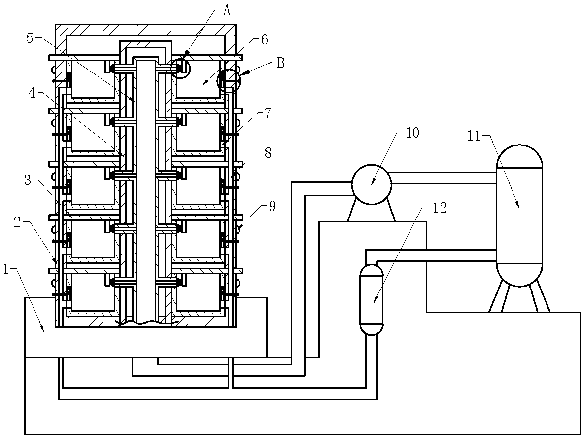
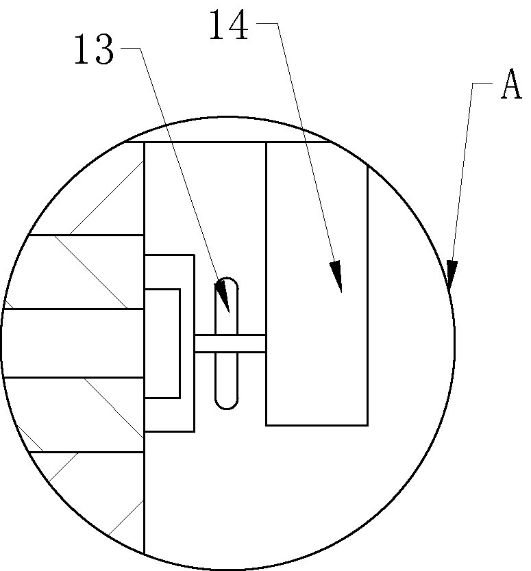
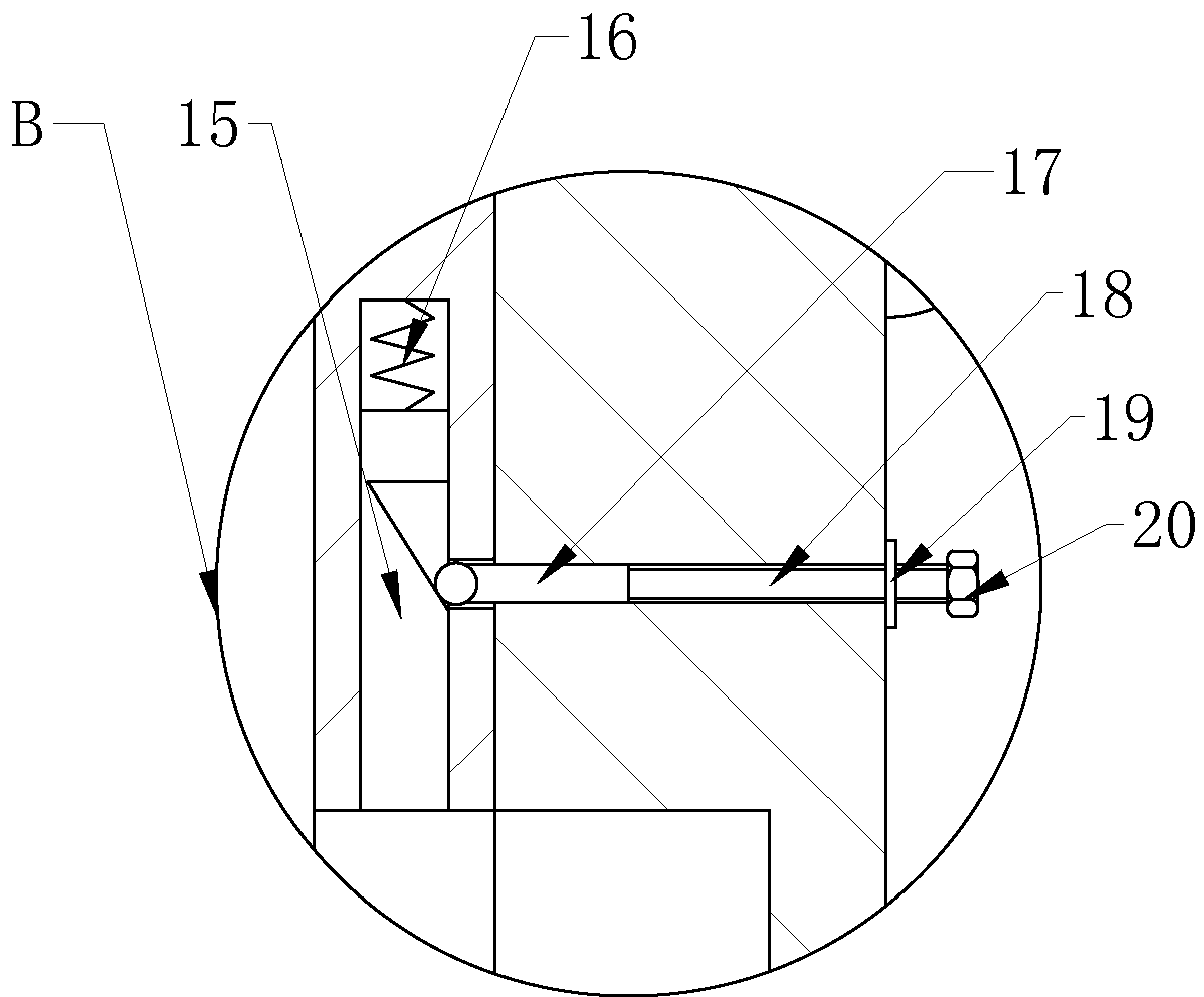
[0022] Example: such as Figure 1-3 As shown, the motor carbon brush sintering furnace includes a base 1 and a furnace body 2. The furnace body 2 is screwed on the base 1 through a threaded rod. There is a cavity in the furnace body 2, and vertical equidistant holes are installed on both sides of the cavity. Arranged sintering pots 6, the top of the sintering pots 6 is slidingly connected with a cover 3, the left end or right end of the cover 3 protrudes from the furnace body 2, and the furnace body 2 between the two rows of sintering pots 6 is welded for heating the sintering pots 6 The electric heating tube 4 is equipped with an electrically connected power supply and buttons in the base 1, and the electric heating tube 4 is electrically connected to the power supply and the buttons. The electric heating tube 4 is provided with a vent pipe 5, and the vent pipe 5 is welded on the furnace body 2. , the ventilation pipe 5 communicates with the upper part of each sintering pot 6...


PUM


Abstract

The invention discloses a motor carbon brush sintering furnace. The motor carbon brush sintering furnace comprises a base and a furnace body, wherein the furnace body is fixed on the base; a cavity is formed in the furnace body; sintering pots which are vertically arranged at equal intervals are arranged on two sides of the cavity; a sealing cover is arranged at the top of each sintering pot; an electric heating tube used for heating the sintering pots is arranged between two columns of sintering pots; a ventilation tube is arranged in the electric heating tube and communicates with the upper part of each sintering pot; a ventilation hole is formed in the bottom of each sintering pot; an exhaust passage is formed in the wall of the furnace body; the ventilation holes communicate with the exhaust passage; the exhaust passage communicates with a filter; the filter communicates with a gas storage tank; the gas storage tank is filled with inert gas and communicates with a gas pump; the gas pump communicates with the ventilation tube. According to the motor carbon brush sintering furnace, the ventilation tube, the filter, the gas storage tank and the gas pump are arranged, so that the inert gas and the heat can be reused; the direct emission of pollutants can be avoided; the sintering temperature in the sintering pots can be ensured; the sintering quality is improved; energy conservation and environmental protection can be achieved.

Description

technical field [0001] The invention belongs to the field of sintering processing equipment, and in particular relates to equipment for sintering carbon brushes of motors. Background technique [0002] At present, motor carbon brushes usually need to be sintered after they are made into shapes. The purpose is to improve the mechanical strength of the product, reduce the resistance and fix its geometry. Smoke, such as: high temperature treatment of resin and asphalt, volatiles, sulfides, carbides, etc. will produce many particles of dust and smoke at high temperature. The firmness of the spot welding in the spot welding process also affects the appearance; the serious pollution of the wire directly leads to the scrapping of the product. [0003] In order to solve the above problems, the Chinese patent application No. 201410093605.X discloses an internal structure of a motor carbon brush sintering furnace, including a sintering furnace body and a furnace furnace. The furnace ...

Claims


Application Information

Patent Timeline
Patent Type & Authority Patents(China)
IPC IPC(8): F27B14/06F27B14/08F27D17/00
CPCF27B14/06F27B14/08F27D17/008
Inventor 曹双全
Owner CHONGQING HEHAI CARBON PROD
Why Eureka
Try Eureka