Liquid cooling device based on serpentine condenser

A serpentine condensing tube and liquid cooling technology, applied in fixed tubular conduit components, lighting and heating equipment, indirect heat exchangers, etc., can solve the problems of slow condensation rate, low efficiency and low efficiency of the condenser, Achieve the effect of improving condensation efficiency, speeding up condensation speed and uniform temperature distribution

Active Publication Date: 2019-03-19
上海电气斯必克工程技术有限公司
View PDF8 Cites 0 Cited by
  • Summary
  • Abstract
  • Description
  • Claims
  • Application Information

AI Technical Summary

Problems solved by technology

[0004] The technical problem to be solved by the present invention is that the condenser efficiency of the traditional single-phase condensing medium is low, and the purpose is to provide a liquid cooling device based on a serpentine condensing tube to solve the problem of slow condensation rate and low efficiency of the condenser of the single-phase condensing medium

Method used


Image

  • Liquid cooling device based on serpentine condenser

Examples


Embodiment 1

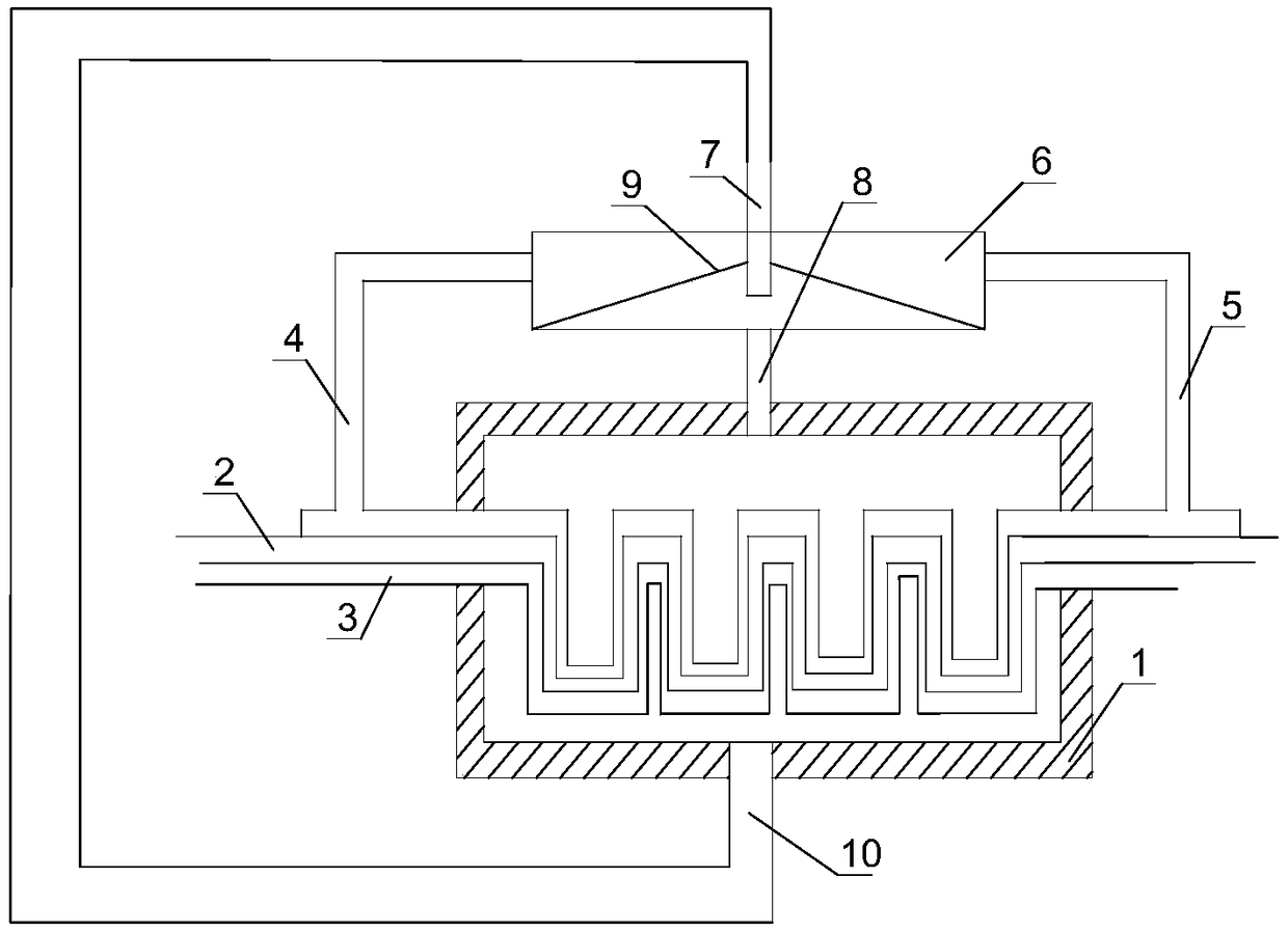
[0022] Such as figure 1 As shown, the liquid cooling device based on the serpentine condenser tube of the present invention includes a condenser 1, a serpentine liquid inlet pipe 2 is installed inside the condenser 1, and a cold air pipe 3 is sleeved on the outside of the serpentine liquid inlet pipe 2 One end of the cold air pipe 3 is connected with an air intake pipe 4, and the air intake pipe 4 is located at one side of the condenser 1, and the other end of the cold air pipe 3 is connected with an air outlet pipe 5 opposite to the air inlet pipe 4, and the air outlet pipe 5 is connected with the air inlet pipe. 4 communicates with an ice chamber 6, the ice chamber 6 is located above the condenser 1, the water inlet pipe 7 is connected above the ice chamber 6, and the water outlet pipe 8 is connected below the ice chamber 6, and the water outlet pipe 8 is connected to the inside of the condenser 1. The cold air pipe 3 inside the condenser 1 is a serpentine pipe that matches ...

Embodiment 2

[0025] Based on Example 1, a partition 9 is installed inside the ice chamber 6, ice cubes are housed in the sealed cavity between the partition 9 and the bottom of the ice chamber, and the water outlet end of the water inlet pipe 7 is located between the partition 9 and the bottom of the ice chamber. In the sealed chamber between them, the air outlet pipe 5 and the air inlet pipe 4 are both in communication with the cavity above the partition 9 .

[0026] The partition divides the ice room into two chambers to facilitate the flow of cold air. After the water inlet pipe is passed into the ice room, the water content in the ice room will increase. If the cold air passes through the ice water, the water content in the cold air will increase. Slow down the flow rate of the cold air. The temperature of the ice water is the combination of tap water and ice. Therefore, the temperature of the ice water in the confinement room will be slightly higher than the temperature of the air-cond...

Embodiment 3

[0028] Based on the above embodiment, a drain pipe 10 is communicated below the condenser 1 , and the lower end of the drain pipe 10 communicates with the water inlet pipe 7 . A temperature sensor is installed inside the condenser 1, and electric valves are installed in the drain pipe 10 and the water inlet pipe 7, and the temperature sensor is connected with the electric valves of the drain pipe 10 and the water inlet pipe 7.

[0029] The drain pipe is used to replace the condensed water in the condenser. The temperature of the condensed water will rise after a period of time. It is necessary to discharge part of the condensed water in the condenser in time and then put fresh ice water into the condenser to keep the condensation inside the condenser. The water is at a lower temperature. The temperature sensor is used to monitor the temperature of the condenser. Once the temperature of the condensed water in the condenser is higher than the preset value, the electric valves in...


PUM


Abstract

The invention discloses a spiral condensing tube-based liquid cooling device, which comprises a condenser, wherein a spiral liquid-inlet pipe is arranged in the condenser; a cold air duct sleeves the spiral liquid-inlet pipe; one end of the cold air duct is communicated with an air-inlet pipe; the air-inlet pipe is positioned on one side of the condenser; the other end, opposite to the air-inlet pipe, of the cold air duct is communicated with an air-outlet pipe; an ice chamber is communicated between the air-outlet pipe and the air-inlet pipe, and is positioned above the condenser; a water-inlet pipe is communicated with the upside of the ice chamber; the downside of the ice chamber is communicated with a water-outlet pipe; the water-outlet pipe is communicated with the interior of the condenser. Because condensate water and cold air are combined, and continuous low temperature of the condensate water and condensate air in the condenser is kept, the condensation speed of the condenser is increased, and the condensation efficiency is improved.

Description

technical field [0001] The invention relates to a refrigeration system, in particular to a liquid cooling device based on a serpentine condenser tube. Background technique [0002] There are two ways to achieve refrigeration, one is natural cooling, and the other is artificial refrigeration. Natural cooling uses natural ice or deep well water to cool objects, but its cooling capacity (that is, the heat removed from the cooled object) and the possible cooling temperature often cannot meet production needs. Natural cooling is a heat transfer process. Artificial refrigeration is a thermodynamic unit operation that uses refrigeration equipment to add energy to transfer heat from a low-temperature object to a high-temperature object. [0003] Liquid cooling is an important production process in chemical production. However, the cooling medium in commonly used condensers is either liquid or gaseous. In the limited condensation path, the cooling speed is slow and the condensation...

Claims


Application Information

Patent Timeline
Patent Type & Authority Patents(China)
IPC IPC(8): F28D7/08F28D7/14F28F27/00
CPCF28D7/085F28D7/14F28F27/00
Inventor 陈杰邓建国王刚新
Owner 上海电气斯必克工程技术有限公司
Why Eureka
Try Eureka