Method for producing three-dimensional plasma photon crystal
A technology of plasma and photonic crystals, which is applied in the field of ionic materials and optics, can solve problems such as failure to form three-dimensional plasma photonic crystals, achieve rich lattice structures and energy level band gaps, wide application fields, and high selectivity strong effect
- Summary
- Abstract
- Description
- Claims
- Application Information
AI Technical Summary
Problems solved by technology
Method used
Image

Examples
Embodiment 1
[0024] Embodiment 1, a method for producing a three-dimensional plasmonic photonic crystal.
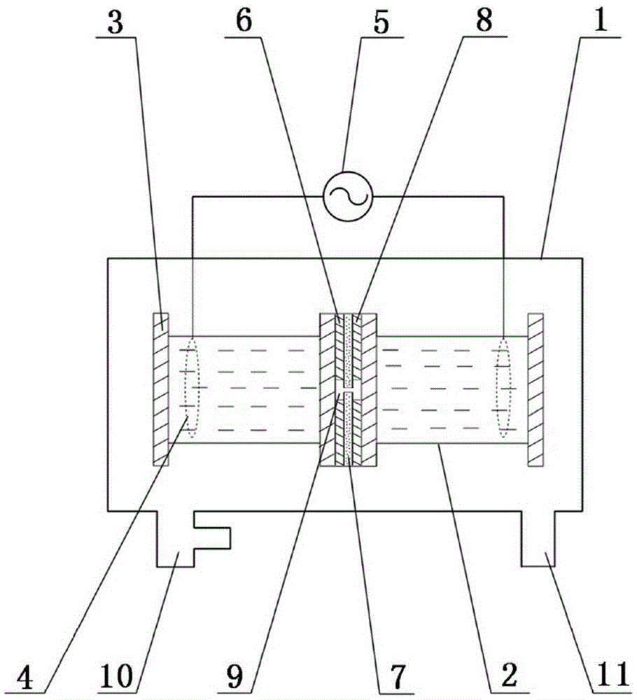
[0025] For the device used in this example, see figure 1 (You can also refer to the prior patent application number 201510878651.5), the method for producing a three-dimensional plasmonic photonic crystal includes the following steps:
[0026] a. A vacuum reaction chamber 1 is provided, an air inlet 10 and an air outlet 11 are provided on the wall of the vacuum reaction chamber 1 , and two water electrodes 2 are installed in the vacuum reaction chamber 1 . The water electrode 2 adopts a plexiglass tube sealed with glass baffles 3 on both sides and filled with water, and a built-in copper ring 4 is electrically connected to the plasma generating power supply 5 .
[0027] b. Between the two water electrodes 2, three layers of left, middle and right layers of glass are sequentially stacked and laminated. On the three layers of glass, a discharge gap 9 with a cavity cross-section in an H...
Embodiment 2
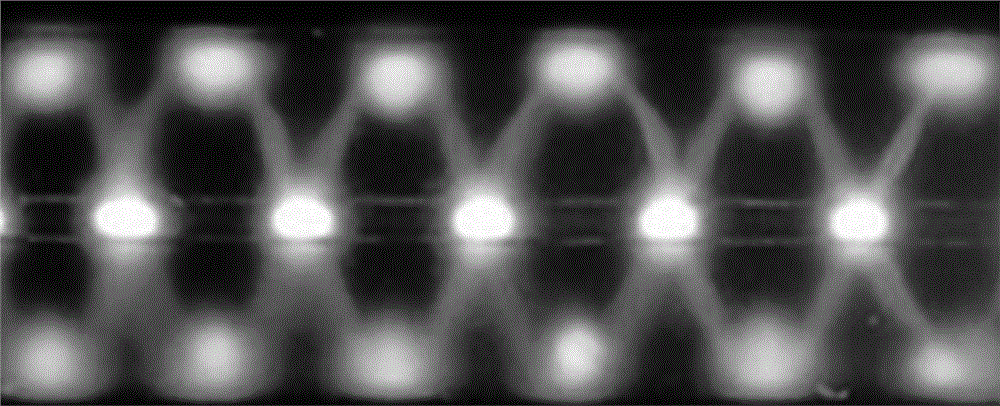
[0039] The present embodiment is compared with embodiment 1, and concrete experimental parameter is: the structure of three layers of glass is figure 1 In the structure shown, the thickness of the three layers of glass is 1.4mm. In the discharge gas in the vacuum reaction chamber 1, the volume content of argon accounts for 5% of the total volume of the discharge gas. The pressure of the discharge gas is 0.12 standard atmospheric pressure, the discharge frequency of the plasma generating power supply 5 is 54kHz, and the effective value of the discharge voltage is 2.72kV.
[0040] The pattern photos of the three-dimensional plasmonic photonic crystals in which straight and oblique plasmonic photonic crystals coexist in the discharge gap produced in this embodiment are as follows image 3 shown. image 3 Among them, the plasmonic photonic crystals at the middle horizontal position (corresponding to the single air gap position) and the plasmonic photonic crystals at the upper an...
Embodiment 3
[0042] Compared with Embodiment 2, this embodiment differs in that: the effective value of the discharge voltage of the plasma generating power supply 5 is 2.36 kV.
[0043] The pattern photos of the three-dimensional plasmonic photonic crystals in which straight and oblique plasmonic photonic crystals coexist in the discharge gap produced in this embodiment are as follows Figure 4 shown. Figure 4 The three-dimensional plasmonic photonic crystal shown in image 3 Similar to the three-dimensional plasmonic photonic crystal in .
PUM
 Abstract
Description
Claims
Application Information
 - R&D
- Intellectual Property
- Life Sciences
- Materials
- Tech Scout
- Unparalleled Data Quality
- Higher Quality Content
- 60% Fewer Hallucinations
Browse by: Latest US Patents, China's latest patents, Technical Efficacy Thesaurus, Application Domain, Technology Topic, Popular Technical Reports.
© 2025 PatSnap. All rights reserved.Legal|Privacy policy|Modern Slavery Act Transparency Statement|Sitemap|About US| Contact US: help@patsnap.com