Permanent magnet synchronous motor rotor position observer for random frequency high-frequency square wave voltage injection

A permanent magnet synchronous motor and square wave voltage technology, which is applied in the direction of motor generator control, electromechanical brake control, electromechanical transmission device control, etc., can solve problems such as noise generation, achieve the effects of reducing noise, reliable use, and broadening the application range

Inactive Publication Date: 2017-06-13
HARBIN INST OF TECH
View PDF4 Cites 28 Cited by
  • Summary
  • Abstract
  • Description
  • Claims
  • Application Information

AI Technical Summary

Problems solved by technology

[0005] The purpose of the present invention is to solve the problem of noise generation in the sensorless control of the existing built-in permanent magnet synchronous motor based on the high frequency signal injection method. The present invention provides a permanent magnet synchronous motor rotor with random frequency high frequency square wave voltage injection position observer

Method used


Image

  • Permanent magnet synchronous motor rotor position observer for random frequency high-frequency square wave voltage injection
  • Permanent magnet synchronous motor rotor position observer for random frequency high-frequency square wave voltage injection
  • Permanent magnet synchronous motor rotor position observer for random frequency high-frequency square wave voltage injection

Examples


Embodiment Construction

[0039]The following will clearly and completely describe the technical solutions in the embodiments of the present invention with reference to the accompanying drawings in the embodiments of the present invention. Obviously, the described embodiments are only some, not all, embodiments of the present invention. Based on the embodiments of the present invention, all other embodiments obtained by persons of ordinary skill in the art without creative efforts fall within the protection scope of the present invention.

[0040] It should be noted that, in the case of no conflict, the embodiments of the present invention and the features in the embodiments can be combined with each other.

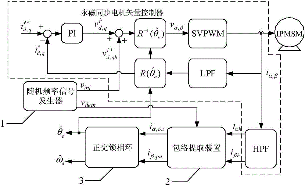
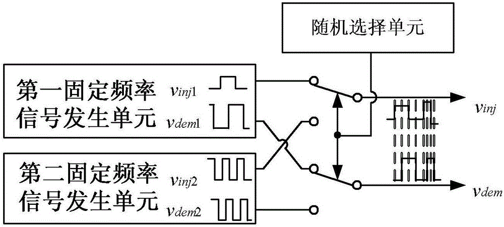
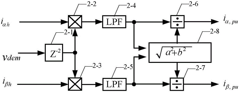
[0041] The present invention will be further described below in conjunction with the accompanying drawings and specific embodiments, but not as a limitation of the present invention. combine figure 1 Describe this embodiment, a permanent magnet synchronous motor rotor position observer with rando...


PUM


Abstract

In order to solve the problem of noise generated in the sensorless control of the existing built-in permanent magnet synchronous motor based on the high frequency signal injection method, a permanent magnet synchronous motor rotor position observer with random frequency high frequency square wave voltage injection is provided, which belongs to the motor control field. The present invention includes: a random frequency signal generator for generating a random frequency injection signal v with the same frequency and phase quadrature inj and a random frequency demodulated signal v dem ; Envelope extraction means for demodulating signal v according to random frequency dem , to extract the α-axis high-frequency current i αh and β-axis high-frequency current i βh The envelope line of the α-axis high-frequency current envelope signal i is obtained α,pu and β-axis high-frequency current envelope signal i β,pu ; Quadrature phase-locked loop 3, used for the high-frequency current envelope signal i according to the α-axis α,pu and β-axis high-frequency current envelope signal i β,pu , to estimate the position of the rotor. The invention can be widely applied to the control system of the built-in permanent magnet synchronous motor, does not need additional hardware, and has obvious effects of reducing noise.

Description

technical field [0001] The invention relates to a rotor position observer of a permanent magnet synchronous motor, in particular to a rotor position observer of a permanent magnet synchronous motor injected with random-frequency high-frequency square wave voltage, belonging to the field of motor control. Background technique [0002] In recent years, AC motors have played an important role in industrial products and household appliances. Compared with the traditional asynchronous motor, the permanent magnet synchronous motor has the advantages of high torque density and high power density, and thanks to the development of permanent magnet material preparation technology in recent years, it occupies an important position in modern industry. Currently, there are various types of permanent magnet synchronous motors used to drive various production equipment such as conveyor belts, robotic arms, cranes, paper mills and wastewater treatment. With the development and progress of ...

Claims


Application Information

Patent Timeline
Patent Type & Authority Applications(China)
IPC IPC(8): H02P21/18H02P21/04
CPCH02P21/04H02P2203/11
Inventor 王高林杨雷赵楠楠张国强徐殿国
Owner HARBIN INST OF TECH
Why Eureka
Try Eureka