Hydraulic gate valve

A gate valve and hydraulic technology, which is applied in the field of hydraulic gate valves, can solve the problems that the thread of the gate valve is easy to wear and get stuck, affects the opening and closing of the gate valve, and the speed of the gate valve is slow, so as to avoid sand washing, reduce pressure loss, and good sealing effect Effect

Inactive Publication Date: 2017-06-16
王翔
View PDF6 Cites 0 Cited by
  • Summary
  • Abstract
  • Description
  • Claims
  • Application Information

AI Technical Summary

Problems solved by technology

[0005] There are many control forms of gate valves. Due to the slow speed of gate valve closing by manual control, the threads of manually controlled gate valves are easy to wear and get stuck, which affects the opening and closing of gate valves.

Method used


Image

  • Hydraulic gate valve

Examples


Embodiment Construction

[0020] The present invention will be described in detail below in conjunction with the accompanying drawings.

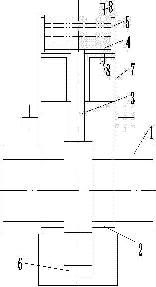
[0021] Such as figure 1 A hydraulic gate valve shown, the hydraulic gate valve includes: valve body 1, valve seat 2, piston rod 3, piston 4, cylinder body 5, gate plate 6, valve frame 7, hydraulic pipe 8, the valve body A valve seat 2 and a gate 6 are installed in 1, a valve frame 7 is installed on the top of the valve body 1, the top of the gate 6 is connected to the bottom end of the piston rod 3, and the top of the piston rod 3 is connected to the piston 4 connection, the piston 4 is installed in the cylinder 5, the cylinder 5 is fixedly installed on the valve frame 7, the top and bottom of the cylinder 5 are provided with hydraulic pipes 8, and the hydraulic pipes 8 are connected with the hydraulic pump The outlet connection of the cylinder body 5 is provided with a reversing valve at the junction of the hydraulic pipe 8 at the top of the cylinder 5 and the hyd...


PUM


Abstract

The invention discloses a hydraulic gate valve. A valve seat and a gate plate are installed in a valve body, a valve frame is installed at the top of the valve body, the top of the gate plate is connected with the bottom end of a piston rod, the top of the piston rod is connected with a piston, the piston is installed in a cylinder body, the cylinder body is fixedly installed on the valve frame, hydraulic pipes are arranged at the top and the bottom of the cylinder body and are connected with an outlet of a hydraulic pump, a reversing valve is arranged at the intersection of the hydraulic pipe at the top of the cylinder body and the hydraulic pipe at the bottom, and an overflow valve is arranged at the outlet of the hydraulic pump. The hydraulic gate valve is reliable in structure, rapid to turn on/off, large in driving force, capable of decreasing flushing of silt to a valve seat hard seal and small in pressure loss.

Description

technical field [0001] The invention relates to the field of valves, in particular to a hydraulic gate valve. Background technique [0002] A valve (famen) is a control component in a fluid delivery system, with functions such as cut-off, regulation, flow diversion, reverse flow prevention, pressure stabilization, diversion or overflow pressure relief. [0003] Valves for fluid control systems, from most Simple There are quite a variety of varieties and specifications of various valves used in various globe valves to extremely complex automatic control systems. Valves can be used to control the flow of various types of fluids such as air, water, steam, various corrosive media, mud, oil, liquid metal and radioactive media. [0004] The control of the valve can adopt a variety of transmission methods, such as manual, electric, hydraulic, pneumatic, turbine, electromagnetic, electro-hydraulic, electro-hydraulic, gas-hydraulic, spur gear, bevel gear drive, etc.; can be driven ...

Claims


Application Information

Patent Timeline
Patent Type & Authority Applications(China)
IPC IPC(8): F16K3/02F16K3/314F16K31/122F16K41/10
CPCF16K3/02F16K3/0227F16K3/314F16K31/122F16K41/10
Inventor 王翔
Owner 王翔
Why Eureka
Try Eureka