Laser displacement sensor

A laser displacement and sensor technology, applied in the field of optical measurement, can solve the problems of being susceptible to vibration and mechanical deformation, high design difficulty, and the laser spot cannot be correctly projected to the sensor, so as to save manufacturing and maintenance costs, reduce design difficulty, and improve accuracy. degree of effect

Active Publication Date: 2017-06-16
NINGBO SUNNY INTELLIGENT TECH CO LTD +1
View PDF2 Cites 1 Cited by
  • Summary
  • Abstract
  • Description
  • Claims
  • Application Information

AI Technical Summary

Problems solved by technology

However, the laser displacement sensor is different from the optical touch screen. With the use of the laser displacement sensor, it is likely that due to vibration, mechanical deformation and other reasons, the light spot emitted by the laser cannot be projected on the sensor correctly, resulting in the inability to perform accurate detection or even complete detection. measurement problem
As for the problems faced by the laser displacement sensor, which are difficult to design and are easily affected by vibration and mechanical deformation, the above patents are helpless
[0007] For the above problems, no effective solution has been proposed

Method used


Image

  • Laser displacement sensor
  • Laser displacement sensor
  • Laser displacement sensor

Examples


Embodiment Construction

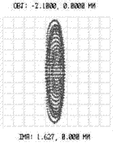
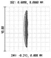
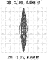
[0036] The description of this illustrative embodiment should be taken in conjunction with the accompanying drawings, which should be considered a part of this complete specification. In the drawings, the shapes or thicknesses of the embodiments may be exaggerated and marked for simplification or convenience. Furthermore, parts of each structure in the drawings will be described separately. It should be noted that elements not shown in the drawings or described in words are forms known to those of ordinary skill in the art.

[0037] The descriptions of the embodiments here, any references to directions and orientations are just for convenience of description, and should not be construed as any limitation to the protection scope of the present invention. The following descriptions of the preferred embodiments involve combinations of features, which may exist independently or in combination, and the present invention is not particularly limited to the preferred embodiments. The...


PUM


Abstract

The invention discloses a laser displacement sensor, which comprises a laser, an imaging objective lens and a photosensitive element, wherein the laser is used for injecting a laser beam; light received and injected by the imaging objective lens is incident to the photosensitive element; when modulation transfer function (MTF) analysis is carried out on the imaging objective lens and the photosensitive element, the analysis result meets the following conditions: in a condition in which the main arrangement direction of multiple photosensitive units of the photosensitive element is a sagittal direction, MTFS>MTFT; in a condition in which the main arrangement direction of multiple photosensitive units of the photosensitive element is a meridional direction, MTFT>MTFS; and the MTFS is the MTF value in the sagittal direction, and the MTFT is the MTF value in the meridional direction. The objective lens design difficulty can be reduced, the manufacturing cost and the maintenance cost are saved, the measurement accuracy is improved, and bad influences caused by vibration or mechanical deformation in the case of use can be better handled.

Description

technical field [0001] The present invention relates to the field of optical measurement, and in particular, to a laser displacement sensor. Background technique [0002] Optical sensors are instruments that measure based on optical principles. This type of sensor has many advantages, such as non-contact and non-destructive measurement, almost uninterrupted measurement, high-speed transmission, telemetry, remote control, and real-time processing. advantage. [0003] Optical sensors include many types. Among them, the laser displacement sensor based on the laser triangulation method is a kind of laser displacement sensor that uses laser light as a light source, CMOS (Complementary Metal Oxide Semiconductor, Complementary Metal Oxide Semiconductor) or CCD (Charge-coupled Device, charge Coupling element) sensor as a precision measuring instrument for the receiver. This kind of sensor can accurately measure the position, displacement and other changes of the measured object wi...

Claims


Application Information

Patent Timeline
Patent Type & Authority Applications(China)
IPC IPC(8): G01B11/02
CPCG01B11/02
Inventor 王雷谭波
Owner NINGBO SUNNY INTELLIGENT TECH CO LTD
Why Eureka
Try Eureka