

Miniaturized broadband dual-polarized antenna feed network
A dual-polarized antenna and feed network technology, applied in the microwave field, can solve problems such as unfavorable engineering applications and occupied space
Active Publication Date: 2017-06-16
LEIHUA ELECTRONICS TECH RES INST AVIATION IND OF CHINA
View PDF7 Cites 3 Cited by
- Summary
- Abstract
- Description
- Claims
- Application Information
AI Technical Summary
Problems solved by technology
This broadens the working frequency band on the one hand, but also takes up a lot of space on the other hand, resulting in the size of the dual-polarized antenna feed network being much larger than the size of the dual-polarized antenna, which is not conducive to engineering applications
Method used
View moreImage
Smart ImageViewing Examples

Examples
specific Embodiment
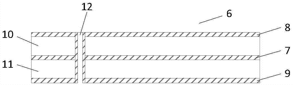
[0025] This embodiment works in the X-band. The overall size of the microstrip board 6 shown in FIG. 3 is 14.5mm×14.5mm×1.016mm, the distance between the ports P2 and P3 is 12.4mm, the length of the groove line 13 is 8.06mm, and the height of the air cavity 5 is 4mm. Rogers RT / duroid 6002 is selected as the dielectric substrate 10 and 11 . The simulation curve of the structure is as Figure 4(a)-Figure 4(c) As shown, within 40% of the bandwidth, the standing wave at the input end is lower than 1.4, the output signal amplitudes of the two output ends are basically the same, and the phase difference is within 180°±0.5°.
Login to View More PUM
 Abstract
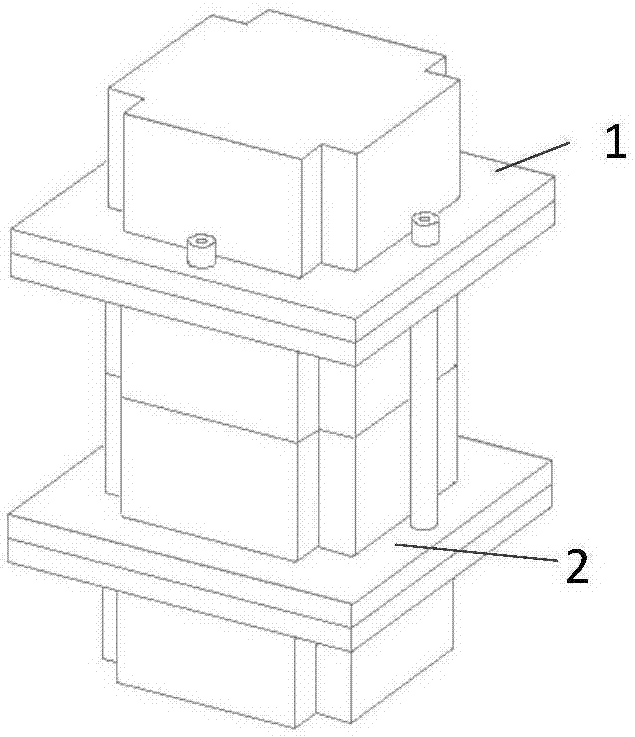
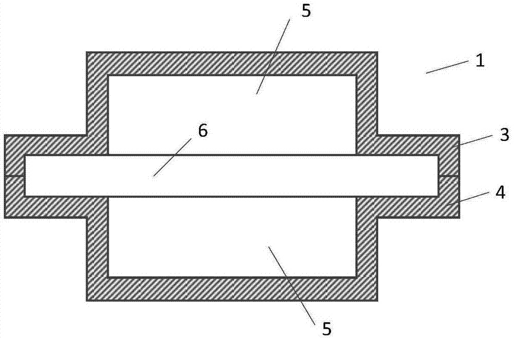
The invention provides a miniaturized broadband dual-polarized antenna feed network, which is formed by an upper-layer three-port network (1) and a lower-layer three-port network (2). The upper-layer three-port network (1) and the lower-layer three-port network (2) are exactly same in structure; and the lower-layer three-port network (2) is arranged in a manner of rotating around a vertical axis for 90 degrees with respect to the upper-layer three-port network (1). According to the feed network, the two ends of a ladder ring for impedance matching are flattened to enable the length of a slot line to be smaller than the distance between ports, at the two ends of a diagonal line, of a dual-polarized antenna, and reduction of the length of the slot line provides space for up-down stack-up arrangement of the two three-port networks, so that the dual-polarized antenna feed network is allowed to be more compact in structure, is fitter to the size of the dual-polarized antenna.
Description
technical field [0001] The invention belongs to the field of microwave technology, and in particular relates to a miniaturized broadband dual-polarization antenna feeding network. Background technique [0002] Dual-polarized antennas are widely used in modern wireless communication systems because of their advantages such as frequency multiplexing, integrated transceiver, polarization diversity, and polarization agility. The development of broadband and miniaturization of dual-polarized antenna puts forward higher requirements for the design of its feed network. [0003] An existing broadband dual-polarized antenna includes four ports distributed at four vertices of a square. A polarization component of the dual-polarized antenna can be excited by simultaneously feeding equal-amplitude and anti-phase signals to the two ports located on the diagonal. In 2008, Kongpop U-yen and others proposed a broadband magic T structure that can output equal-amplitude anti-phase signals i...
Claims
Login to View More Application Information
Patent Timeline
 IPC IPC(8): H01Q1/48H01Q1/50
Inventor周丹晨张兆成孙丹
OwnerLEIHUA ELECTRONICS TECH RES INST AVIATION IND OF CHINA